High tenacity yarn and method of manufacturing glove using same

Active Publication Date: 2021-09-28
KIM YONG GUN
View PDF31 Cites 1 Cited by
  • Summary
  • Abstract
  • Description
  • Claims
  • Application Information

AI Technical Summary

Benefits of technology

The patent describes a method for making a high tenacity yarn by using a first covering yarn and a second covering yarn, which are made of metal components. The second covering yarn is heat-treated to make it easier to pass through the knitting machine. By using a specific metallic combination, the yarn has both sufficient tenacity and flexible capacity. The technical effect of this method is that it allows for the production of thin, high-tensacity gloves using a metallic yarn core.

Problems solved by technology

However, a price of the HPPE fiber is higher than that of a nylon fiber or polyester fiber, thereby resulting in an increase in manufacturing costs in mass production.
On the other hand, the nylon fiber or the polyester fiber is cheaper than the HPPE fiber and is capable of being made of a product having a thickness thinner than that of the HPPE fiber, but a tenacity thereof is weak, so that the nylon fiber or the polyester fiber is not currently used as a core yarn for manufacturing a high tenacity glove.
In addition, there is a problem in that it is difficult to knit a glove and the like by using a yarn in which a glass fiber is used as a core yarn.
This is because the yarn in which the glass fiber is used as a core yarn is fragile and a powder is discharged when it is broken.
This is because it is difficult to keep the metallic yarn from breaking during a manufacturing process.
In addition, a thickness of the core has to be thickened to secure a sufficient tenacity, so that it is not possible to use an 18-gauge knitting machine.
Therefore, there is a problem in that it is not possible to knit a glove having a finer structure.

Method used


Image

  • High tenacity yarn and method of manufacturing glove using same
  • High tenacity yarn and method of manufacturing glove using same
  • High tenacity yarn and method of manufacturing glove using same

Examples


Embodiment Construction

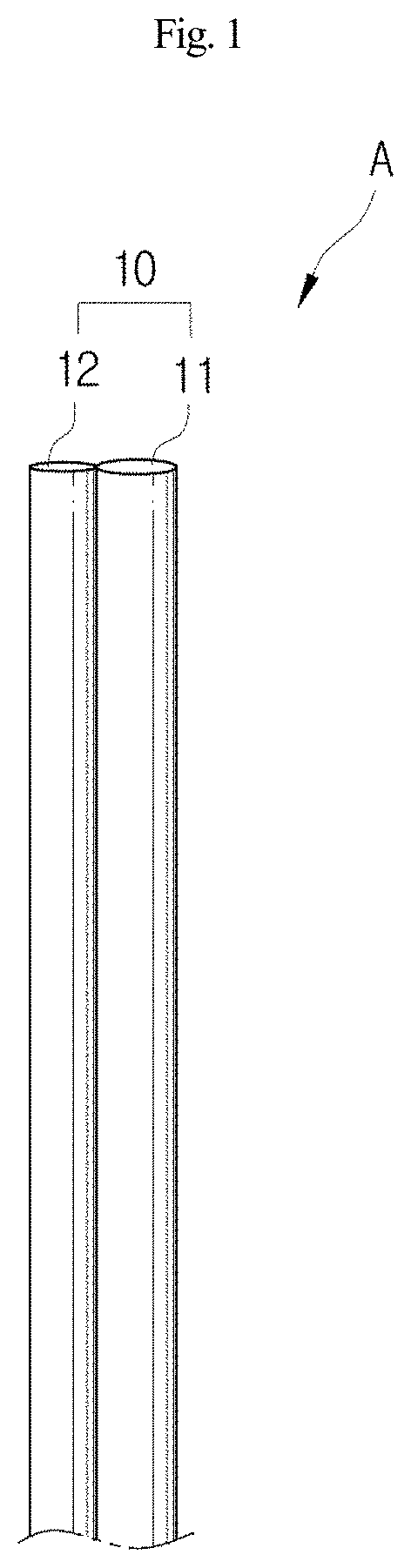
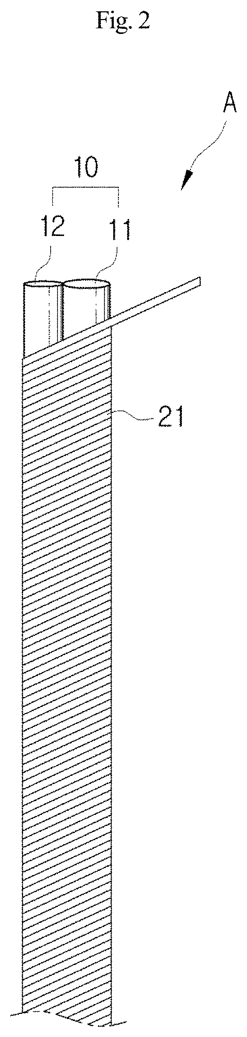
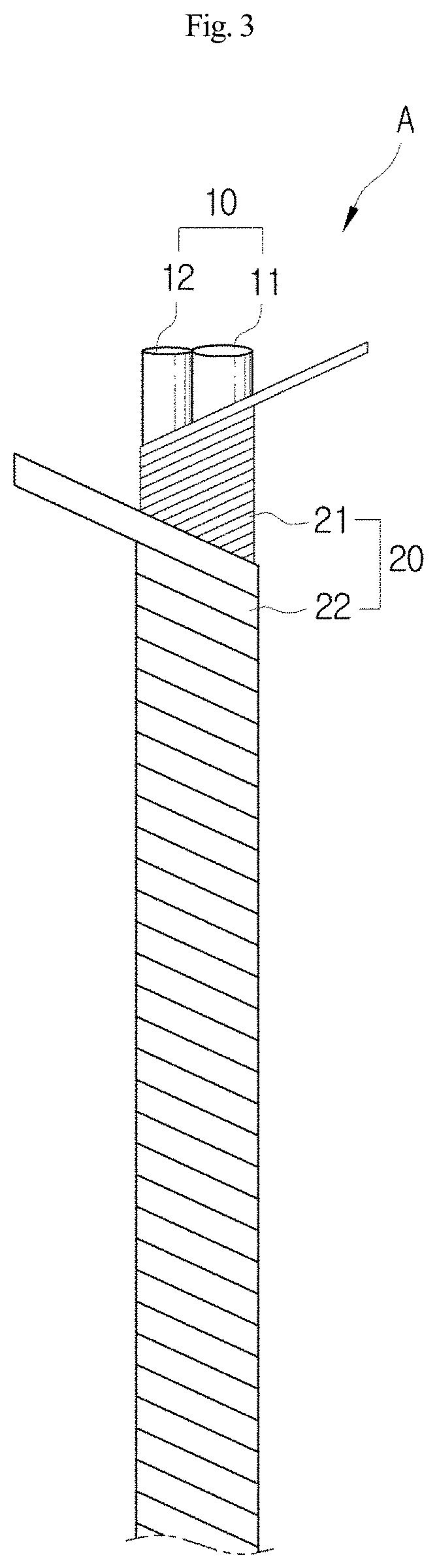
[0031]In the present disclosure, there is proposed a high tenacity yarn that is capable of being knitted finely and thinly even if a metallic yarn is used as a core of a main yarn. To this end, the high tenacity yarn includes a core yarn and a covering yarn wound on a circumference of the core yarn. The core yarn includes a first core yarn part formed of a metal component and a second core yarn part formed of a metal component, and a total thickness of the first core yarn part and the second core yarn part is formed to be 0.07 mm or less.

[0032]In addition, a method of manufacturing a glove by using the high tenacity yarn is proposed. The glove is manufactured by double-knitting of the high tenacity yarn as a main yarn together with auxiliary yarns by using a knitting machine. In a hand part of the glove, an auxiliary yarn used in knitting the hand part includes an auxiliary core yarn formed of a spandex yarn, and an auxiliary covering yarn wound on the auxiliary core yarn and formed...


PUM

PropertyMeasurementUnit
Temperatureaaaaaaaaaa
Lengthaaaaaaaaaa
Linear densityaaaaaaaaaa

Abstract

Proposed are a high tenacity yarn and a method of manufacturing a glove using the same. More particularly, proposed are a high tenacity yarn capable of being knitted finely and thinly and having a high tenacity even if a metallic yarn is used as a core of a main yarn, and a method of manufacturing a glove using the same. To this end, the high tenacity yarn includes a core yarn and a covering yarn wound on a circumference of the core yarn. The core yarn includes a first core yarn part formed of a metal component and a second core yarn part formed of a metal component, and a total thickness of the first core yarn part and the second core yarn part is formed to be 0.07 mm or less.

Description

CROSS REFERENCE TO RELATED APPLICATION[0001]The present application claims priority to Korean Patent Application No. 10-2020-0176555, filed Dec. 16, 2020, the entire contents of which is incorporated herein for all purposes by this reference.BACKGROUND OF THE INVENTIONField of the Invention[0002]The present disclosure relates to a high tenacity yarn and a method of manufacturing a glove using the same and, more particularly, to a high tenacity yarn capable of being knitted finely and thinly and having a high tenacity, and a method of manufacturing a glove using the same.Description of the Related Art[0003]In general, a coated glove denotes a glove which is formed by coating a surface of a knitted glove knitted with a nylon yarn, a spandex yarn, a cotton yarn, a polyester yarn, a glass fiber, or the like to impart abrasion resistance, tear strength, puncture resistance, slip resistance, air permeability, a waterproof function, and the like.[0004]In addition, in industrial fields requ...

Claims


Application Information

Patent Timeline
IPC IPC(8): D02G3/38D02G3/12D02G3/44D04B1/28
CPCD02G3/38D02G3/12D02G3/442D04B1/28D10B2501/041A41D19/01505D02G3/328A41D31/24D02G3/36D02G3/26D02G3/34D04B1/14D04B1/16D04B1/18D10B2401/063
Inventor KIM, YONG GUN
Owner KIM YONG GUN
Why Eureka
Try Eureka