Supercharge Your Innovation With Domain-Expert AI Agents!

System and method for manufacturing a part

a manufacturing system and technology for parts, applied in the field of systems and methods for manufacturing parts, can solve the problems of reducing the flexibility of the process, affecting the quality of the part,

Active Publication Date: 2021-10-05
GRID LOGIC
View PDF1 Cites 2 Cited by
  • Summary
  • Abstract
  • Description
  • Claims
  • Application Information

AI Technical Summary

Benefits of technology

This approach enables the cost-effective and flexible manufacture of high-strength metal parts in various sizes, reducing the need for complex equipment and skilled labor, while ensuring the quality and structural integrity of the produced components.

Problems solved by technology

Thermoplastic-based SFF technologies allow designers to verify product design with three-dimensional models at an early stage, but are not capable of fabricating high-strength end products.
However, in both SLS and DMD technologies, the entire unfused components or particles that comprise the powdered material is heated indiscriminately by the high intensity laser beam.
In certain applications, such as when the powdered material includes a ceramic component, the laser may cause thermal decomposition of the ceramic part resulting in the degradation of the physical characteristics of the macroscopic part.
This requirement severely limits the flexibility of the process, especially if parts need to be fabricated in factory environments, depots, or FOBs.Scalable Build Envelope The need for a controlled atmosphere build chamber limits the overall size of the parts that can be fabricated and prevents the system from being easily scaled to very large parts.Low Operations Burden Many AM systems are complex machines with a myriad of operating parameters that ultimately effect the quality of the additively manufactured part.
In addition, these systems require constant monitoring, frequent maintenance, and skilled technicians to run efficiently, which add considerable cost to the final part produced.Part Qualification Unlike metal parts that are fabricated using casting and / or conventional subtractive machining, AM parts are fabricated through as-yet unqualified processes for many applications, which may delay the adoption of these parts.

Method used


Image

  • System and method for manufacturing a part
  • System and method for manufacturing a part
  • System and method for manufacturing a part

Examples


Embodiment Construction

Induction Heating of Fine Metal Powders

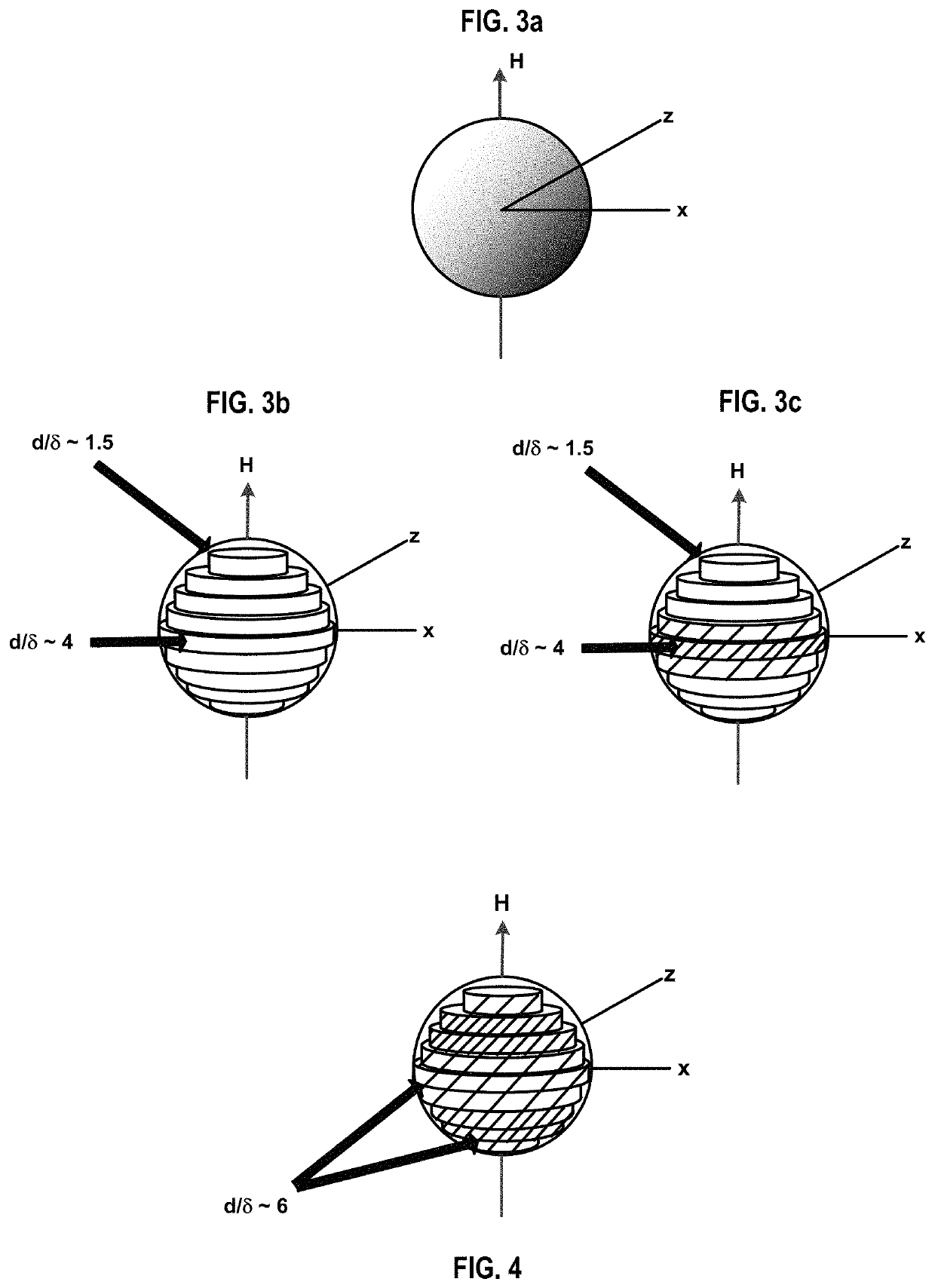
[0088]Micro-Induction Sintering (MIS) is a new additive manufacturing process described herein in which a metallic powder is consolidated via high frequency induction heating. Unlike laser- or electron beam-based additive manufacturing techniques in which the metal powder is heated indiscriminately by an external energy source, the MIS technique allows for the selective heating of individual particles by tailoring the frequency of an applied magnetic field. A localized high frequency magnetic field is produced at the powder bed using a specifically designed flux concentrator (FC) system.

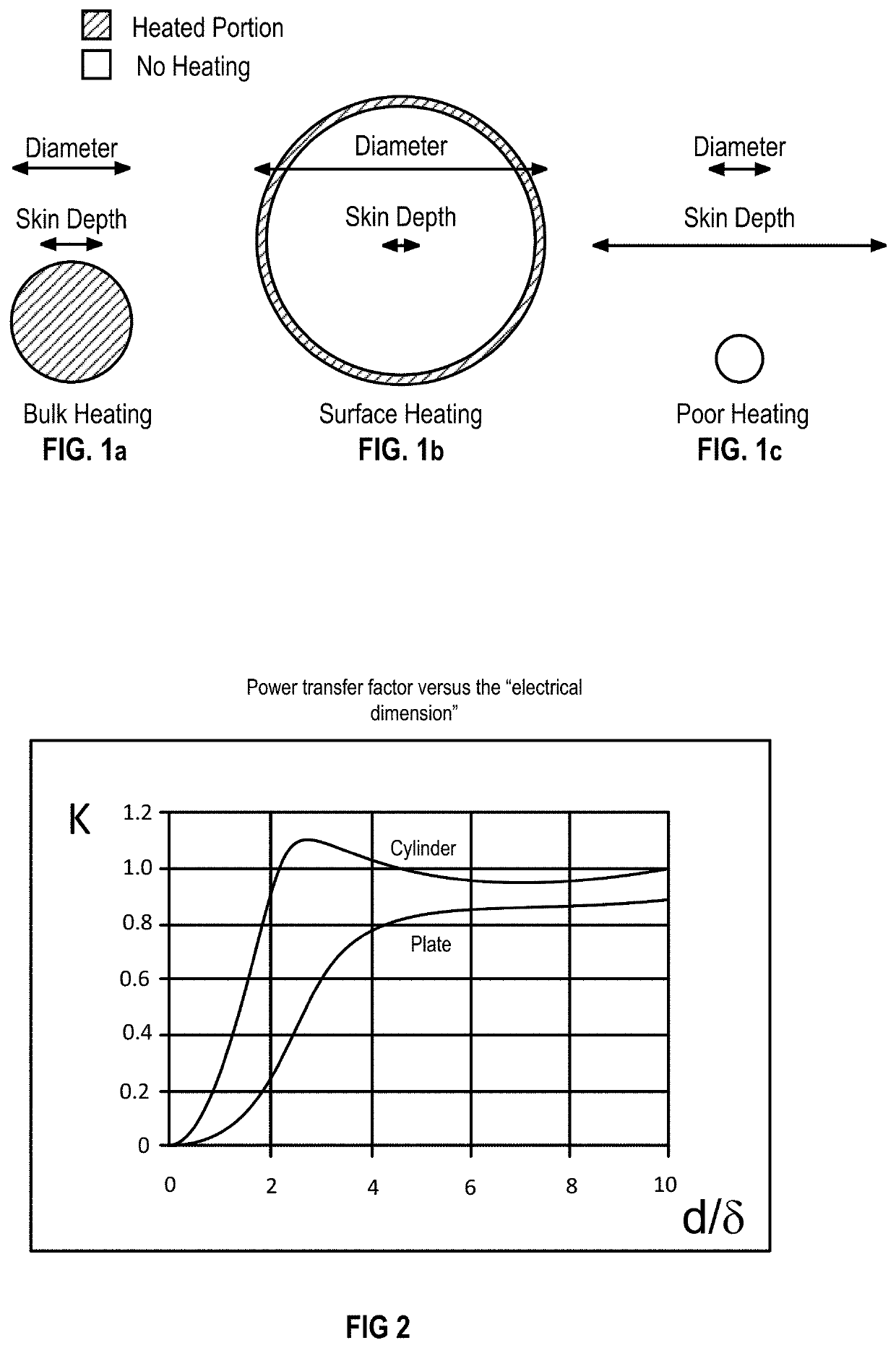
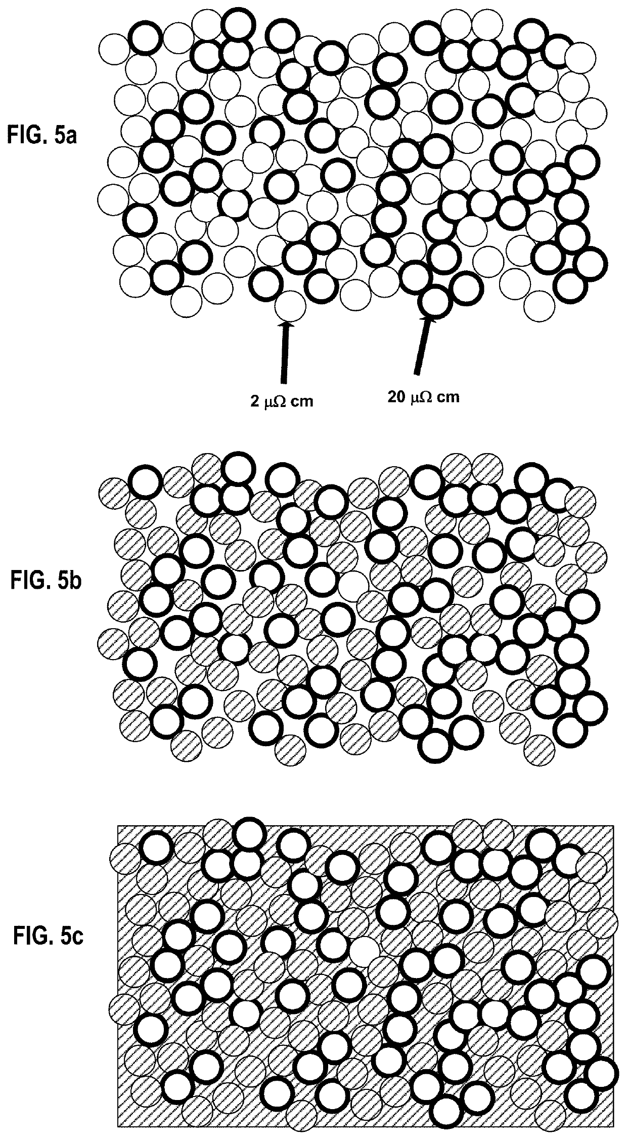
[0089]Heating of metallic particles by induction is a result of both Joule heating due to eddy currents in non-magnetic metallic particles and hysteresis loss in magnetic particles, both of which result from the application of a high frequency magnetic field. For non-magnetic metals, eddy currents flow within a certain distance from the surface of the material. ...


PUM

PropertyMeasurementUnit
electrical resistivitiesaaaaaaaaaa

Abstract

A mould-forming and sacrificial materials are printed into a plurality of layers. The sacrificial material is removed to leave a void defined by a mould structure formed by the mould-forming material. The void is filled with a part-forming material to form the part defined by the shape of the mould structure. The mould structure is removed from the part to free the part from the mould structure. According to a further method, the part-forming material serves the purpose of supporting the mould-forming material and then forming the part. In this case, the part-forming material can be printed together with a mould-forming material as described above and are then heated to a temperature of approximately 700° C. to activate a binder and then heated to a temperature that melts the part-forming material.

Description

CROSS-REFERENCE TO RELATED APPLICATIONS[0001]This application claims priority from U.S. Provisional Patent Application No. 62 / 625,749, filed on Feb. 2, 2018, all of which is incorporated herein by reference in its entirety.BACKGROUND OF THE INVENTION1). Field of the Invention[0002]This invention relates to a system and method for manufacturing a part.2). Discussion of Related Art[0003]It has become common place to fabricate three-dimensional components using Computer Numerical Control (CNC) systems. State of the art solid freeform fabrication (SFF) methods span a number of technologies including stereolithography, 3D printing, selective laser sintering, direct metal deposition, electron beam melting, and microplasma powder deposition. Thermoplastic-based SFF technologies allow designers to verify product design with three-dimensional models at an early stage, but are not capable of fabricating high-strength end products. In principle, metal-based SFF technologies allow for the rapid...

Claims


Application Information

Patent Timeline
Patent Type & Authority Patents(United States)
IPC IPC(8): B22C9/04B22C9/22B22C7/02B33Y10/00B33Y70/00B33Y80/00B22F3/105B22F10/10
CPCB22C9/043B22C7/02B22C9/22B22F3/105B22F10/10B33Y10/00B33Y70/00B33Y80/00B22F2003/1053B22F2999/00Y02P10/25B22F12/10B22F12/52B22F12/55B22F12/90B22F10/28B22F10/16B22F2202/07
Inventor HOLCOMB, MATTHEW JAMESHOLCOMB, JR., IRA JAMES
Owner GRID LOGIC
Features
  • R&D
  • Intellectual Property
  • Life Sciences
  • Materials
  • Tech Scout
  • Unparalleled Data Quality
  • Higher Quality Content
  • 60% Fewer Hallucinations
Learn More