Image capturing device

Active Publication Date: 2021-10-19
MITSUBISHI ELECTRIC CORP
View PDF4 Cites 0 Cited by
  • Summary
  • Abstract
  • Description
  • Claims
  • Application Information

AI Technical Summary

Benefits of technology

The present disclosure describes a device that can capture images effectively by selecting the best method for correcting any angular deviation or Euler angle where it happens. This results in a high degree of accuracy and efficient correction of the device's angle of view.

Problems solved by technology

Because of such manual restoration, not only the time for restoring the camera to the state before the image deviation, but also the personnel expenses are required.
Moreover, because a strict adjustment to the angle of view is required of image capturing devices intended for surveillance systems, the restoration is greatly influenced by worker's skill and it is very difficult to adjust the angle of view to the original one with a high degree of accuracy.

Method used


Image

  • Image capturing device
  • Image capturing device
  • Image capturing device

Examples


embodiment 1

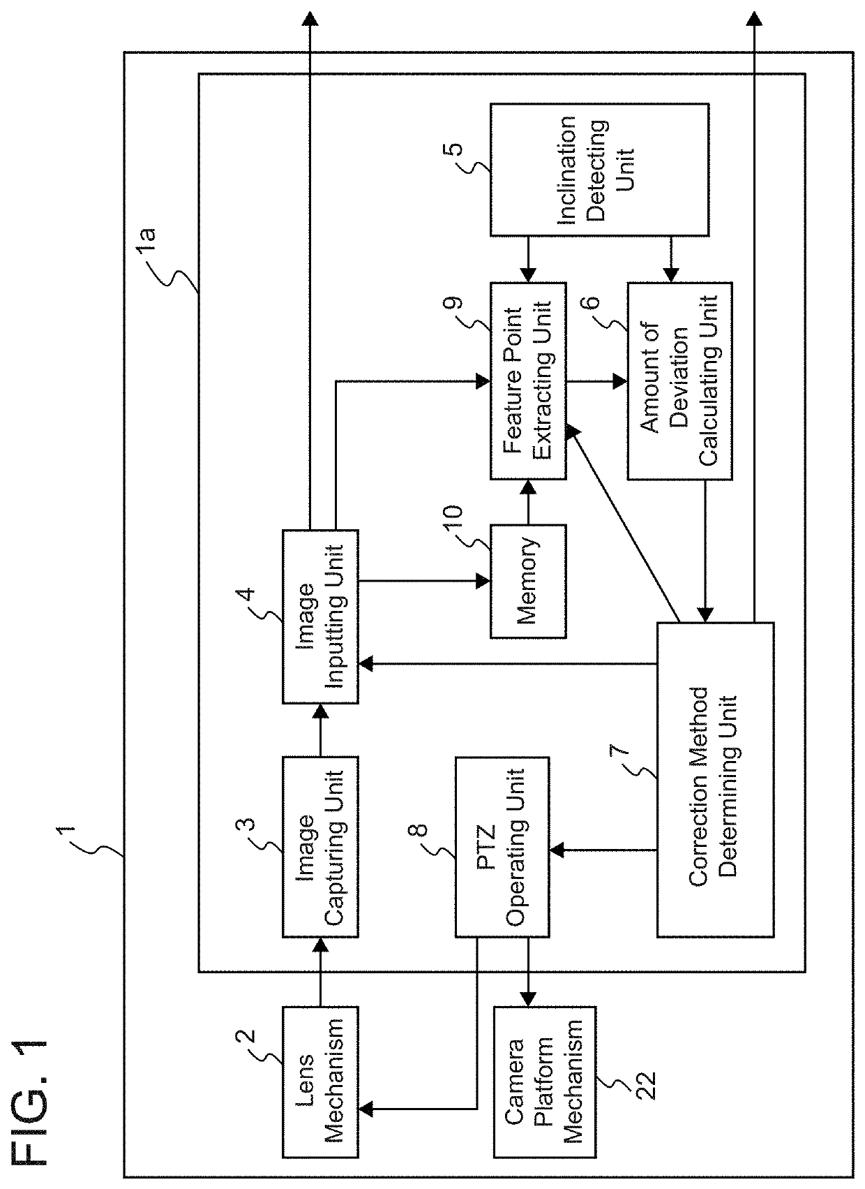
[0019]FIG. 1 is a block diagram showing the configuration of an image capturing device according to Embodiment 1 of the present disclosure.

[0020]As shown in FIG. 1, the image capturing device 1 includes an image capturing device control unit 1a, a lens mechanism 2, and a camera platform mechanism 22. The camera platform mechanism 22 maintains the posture of the image capturing device 1. The lens mechanism 2 transmits an image of an object to be captured to the image capturing device control unit 1a. The image capturing device control unit 1a includes an image capturing unit 3, an image inputting unit 4, an inclination detecting unit 5, an amount of deviation calculating unit 6, a correcting method determining unit 7, a pan tilt zoom operating unit (PTZ operating unit) 8, a feature point extracting unit 9, and a memory 10.

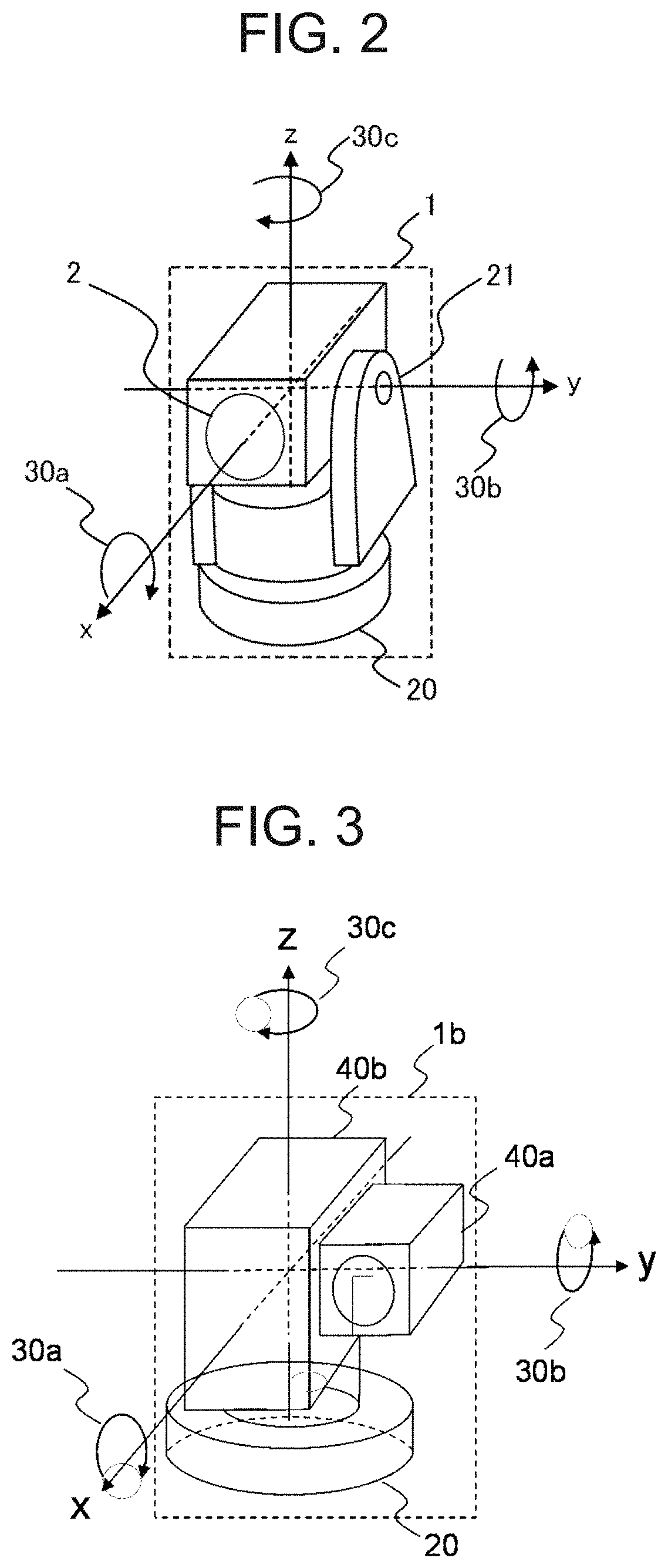
[0021]Further, the image capturing device 1 according to Embodiment 1 is assumed to be a swivel surveillance camera that performs control via a communication networ...

embodiment 2

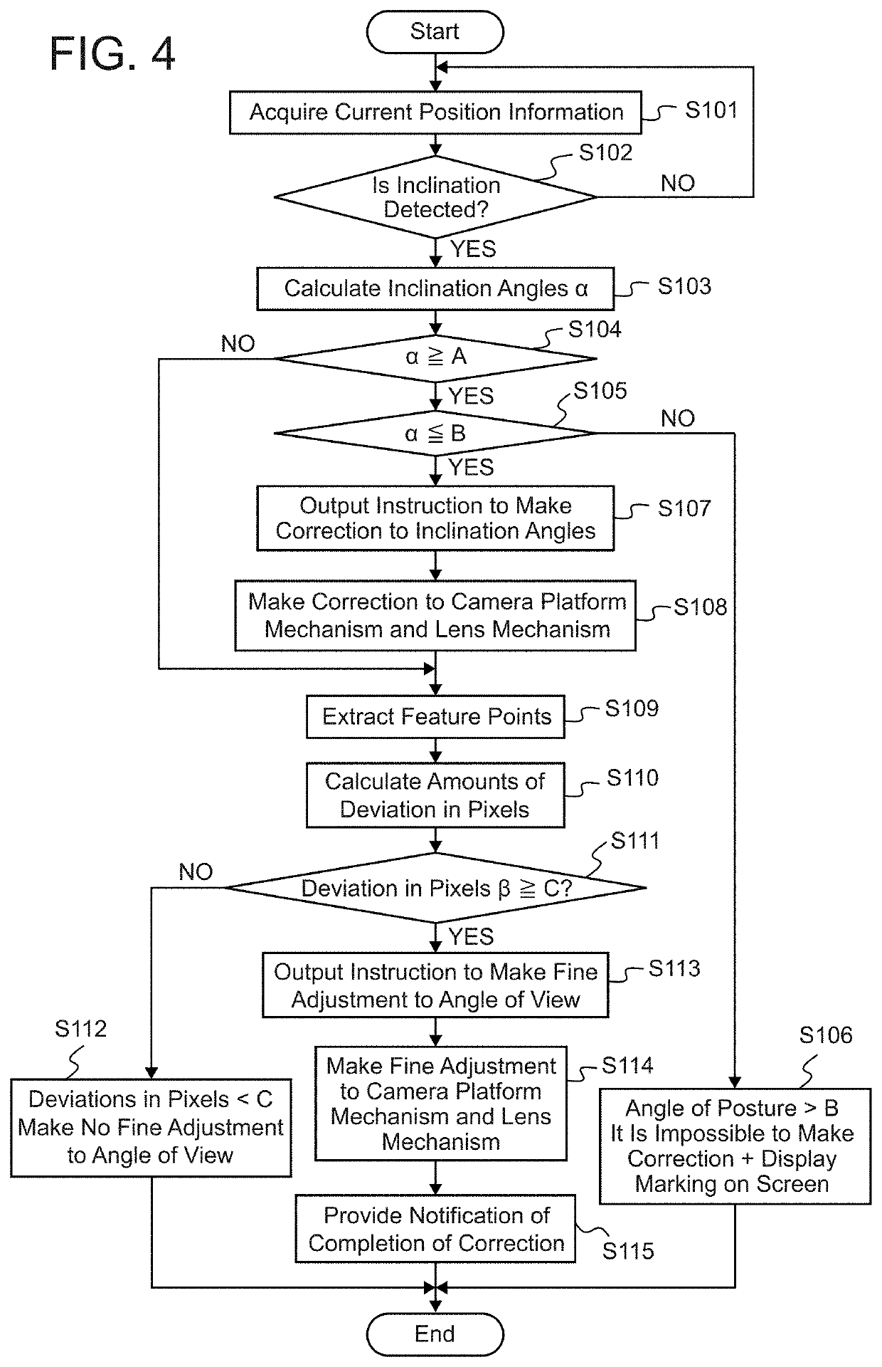
[0055]In Embodiment 1, the image capturing device 1 periodically observes a change of its posture, and, when its inclination is detected and it is then determined that it is necessary to make an adjustment to the angle of view, automatically makes a correction to the inclination of the posture of the image capturing device and, after that, makes a fine adjustment to the angle of view.

[0056]In an image capturing device according to Embodiment 2, the image capturing device 1, when its inclination is detected, either makes corrections starting from an inclination correction to the posture, like that of Embodiment 1, or makes only a fine adjustment to the angle of view, by making a selection after determining a correcting method having a shorter processing time.

[0057]Because the configuration of the image capturing device according to this Embodiment 2 is the same as that of the image capturing device according to Embodiment 1 shown in FIG. 1, an explanation of the configuration will be...


PUM


Abstract

An image capturing device includes inclination detecting circuitry to detect an inclination from a reference position and output the inclination as angle data; feature point extracting circuitry to extract, based on both a reference position image and a current position image, respective feature points; amount of deviation calculating circuitry to calculate an inclination angle based on the angle data, and calculating an amount of deviation in pixels on the basis of the feature points; and correcting method determining circuitry to, when it is determined that the inclination angle is within a range in which the angle can be corrected, the range being equal to or greater than a lower limit and equal to or less than an upper limit, provide a correction instruction to make a correction to the inclination angle and then to make a fine adjustment to the inclination of the angle of view.

Description

CROSS-REFERENCE TO RELATED APPLICATION[0001]The present application is based on PCT filing PCT / JP2018 / 026687, filed Jul. 17, 2018, the entire contents of which are incorporated herein by reference.TECHNICAL FIELD[0002]The present disclosure relates to an image capturing device that makes a correction to an inclination of the angle of view with a high degree of accuracy, the inclination being caused by an external force, a vibration, or the like.BACKGROUND ART[0003]In conventional image capturing devices provided with an image sensor such as a CCD, camera platforms that can rotate are provided, a PTZ (in a PAN direction, in a TILT direction, and in a ZOOM direction) operation can be performed on the camera platforms, and the image capturing devices are usually installed in an outdoor or indoor environment for surveillance uses.[0004]When an image capturing device is installed, image capturing is started after the angle of view is adjusted so that a desired object image can be capture...

Claims


Application Information

Patent Timeline
IPC IPC(8): H04N5/232
CPCH04N5/23299H04N5/23254H04N5/23261H04N7/18H04N23/80H04N23/69H04N23/695H04N23/6811H04N23/6815
Inventor HASHIMOTO, MITSUO
Owner MITSUBISHI ELECTRIC CORP
Why Eureka
Try Eureka