

Apparatus and methods for three dimensional plasthesis prostheses
a three-dimensional, prosthesis technology, applied in the field of prosthesis, radiation boluse, presurgical model, burn mask, etc., can solve the problem of multiple office visits of patients
- Summary
- Abstract
- Description
- Claims
- Application Information
AI Technical Summary
Benefits of technology
Problems solved by technology
Method used
Image

Examples
examples
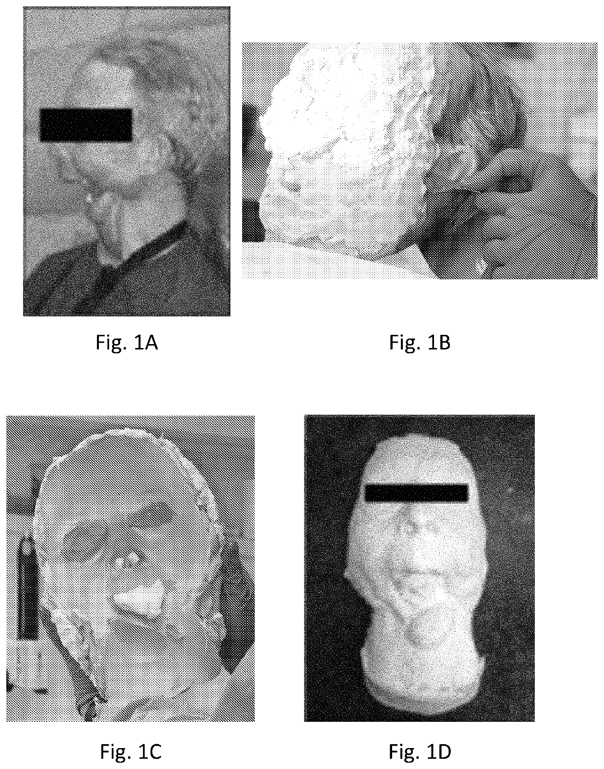
[0147]A maxillofacial prosthesis was designed and formed using method 50 (FIG. 6) for the patient pictured in FIG. 1A using a 3dMDface stereophotogrammetry system as the scanning apparatus 32 and a 3D printer as the rapid prototyping device 36. FIG. 8A illustrates an image of the patient of FIG. 1A wearing a traditionally molded prosthesis captured using a photogrammetry scanner, a 3dMDface stereophotogrammetry system. FIG. 8A was used as a reference image in crafting the new prosthesis 10. FIG. 8B illustrates a view of a portion of the scan data from FIG. 8A showing a front view of the patient using the ZBrush software program. FIG. 8C illustrates another view of the portion of the scan data from FIG. 8B showing an overhead view of the topographical data of the patient using the ZBrush software program.
[0148]FIG. 8D illustrates an image of the patient of FIG. 1A without the traditionally molded prosthesis shown in FIG. 8A. FIG. 8D was also captured using the 3dMDface stereophotogra...
PUM
 Abstract
Description
Claims
Application Information