
Rotary converter of wind energy with a vertical axis of rotation

a technology of wind energy and rotary converter, which is applied in wind power generation, greenhouse gas reduction, renewable energy generation, etc., can solve the problems of affecting the cost of electricity produced by, the possibility and effectiveness of the turbine, and the wide range of use of the turbine, so as to achieve the control of the impact of the wind and torque on the shovel, the control of the size of the flag, and the control of the effect of the wind and torqu

Active Publication Date: 2021-11-16
DYULGERSKI ALEKSEY SLAVOV
View PDF26 Cites 0 Cited by
  • Summary
  • Abstract
  • Description
  • Claims
  • Application Information

AI Technical Summary

Benefits of technology

[0002]The preservation of nature and the depletion of energy resources increases the demand for renewable energy sources. The use of wind power for the production of electricity is one of the possible alternatives of the environment-polluting methods. When applying wind power, the kinetic energy of the wind is most often converted into rotational motion of a rotor, which drives an electrical generator. Horizontal-axis wind turbines are the devices most often employed to convert wind energy in to electrical power. They also hold the main share in wind energy production. The large size of horizontal-axis wind turbines which their blades can reach is one of the advantages which they have. This allows them to catch and convert significant quantities of wind energy.
[0008]The variable flag-formed working surface of the shovels allows them to have different drag depending which sides of the shovels are facing the wind.

Problems solved by technology

All this makes construction and operation of horizontal-axis wind turbines expensive and affects the cost of electricity produced by them.
Their possibilities and their effectiveness, however haven't allowed them to receive wide range of use.
The a reason for this is their inability to convert large amounts of wind energy.

Method used


Image

  • Rotary converter of wind energy with a vertical axis of rotation
  • Rotary converter of wind energy with a vertical axis of rotation
  • Rotary converter of wind energy with a vertical axis of rotation

Examples


Embodiment Construction

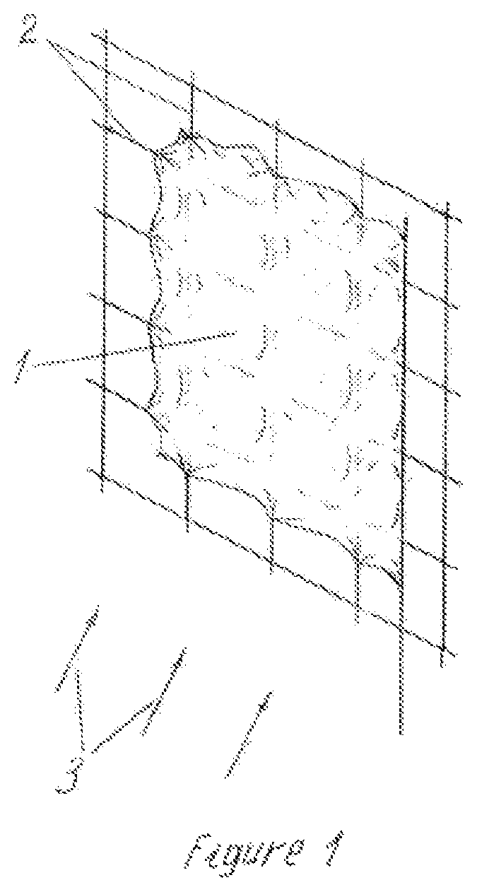
[0024]FIG. 1 shows a flag 1 and wind-permeable structure 2, which limits the capability of the flag to take the direction of the wind 3 into certain directions. Pressed to the structure, the flag forms a surface, which prevents the passage of the air flow. This surface increases the air resistance of the structure and the impact of the wind on it. The surface is variable because its forming depends on the capability of the flag to take the direction of the airflow. When the flag has this capability, such surface is not formed. The airflow passes through the structure by meeting minimum resistance. The variable flag-formed surface changes the air resistance as well as the impact of the wind to the structure. When this impact causes a movement of the structure, this surface is called “working surface”, or “variable flag-formed working surface”.

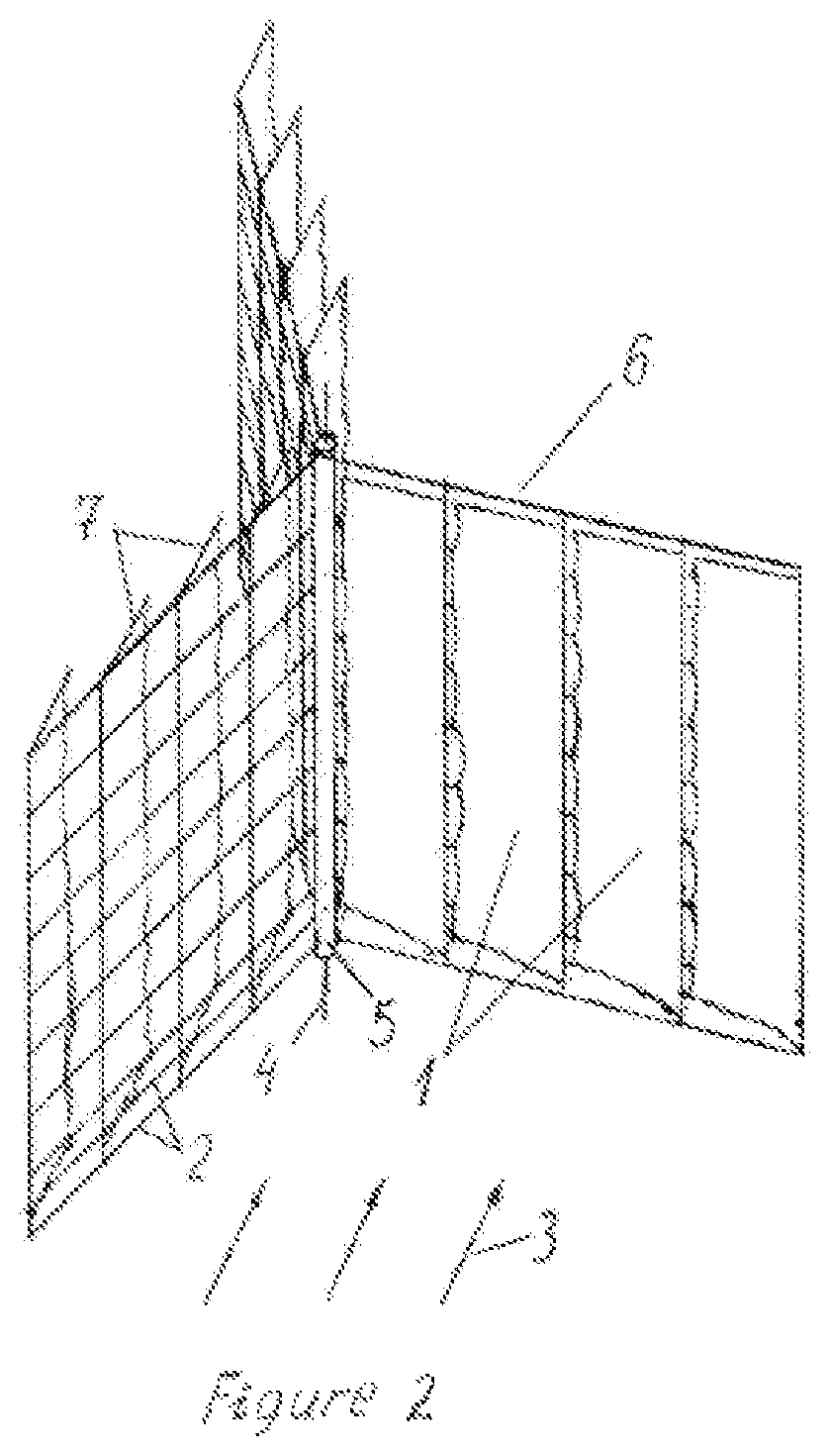
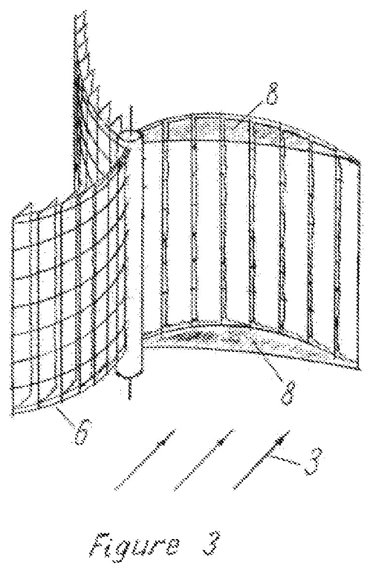
[0025]FIG. 2 shows a rotary converter of wind energy with a vertical axis of rotation, having shovels with a variable flag-formed working surfa...


PUM


Abstract

A rotary converter of wind energy with a vertical axis of rotation includes a rotor with a vertical axis of rotation 4, which has two or more shovels 6 connected to a central body 5 and / or to each other. The shovels called “working” shovels have wind-permeable structure 2. On one side of the shovels is formed a working surface. It is formed on same side of all working shovels by a flag or flags 1 of which the structure limits the capability to take the direction of the air flow, meeting with this side of the shovels. By this surface, the shovels catch the wind energy and convert it to a rotational motion of the rotor. The shovel's load and the rotor speed can be regulated.

Description

[0001]This invention relates to a device for converting wind power into a rotational motion of a rotor with a vertical axis of rotation.[0002]The preservation of nature and the depletion of energy resources increases the demand for renewable energy sources. The use of wind power for the production of electricity is one of the possible alternatives of the environment-polluting methods. When applying wind power, the kinetic energy of the wind is most often converted into rotational motion of a rotor, which drives an electrical generator. Horizontal-axis wind turbines are the devices most often employed to convert wind energy in to electrical power. They also hold the main share in wind energy production. The large size of horizontal-axis wind turbines which their blades can reach is one of the advantages which they have. This allows them to catch and convert significant quantities of wind energy.[0003]Their principal of work, however, has some disadvantages. For the appearance of a to...

Claims


Application Information

Patent Timeline
Patent Type & Authority Patents(United States)
IPC IPC(8): F03D3/06
CPCF03D3/068F03D3/067Y02E10/74F03D3/005
Inventor DYULGERSKI, ALEKSEY SLAVOV
Owner DYULGERSKI ALEKSEY SLAVOV
Learn More