Redundant projected capacitive touch panel

a capacitive touch panel and capacitive technology, applied in the field of capacitive touch panel displays, can solve the problems of electromagnetic interference (emi) and emc, stringent requirements, and use of such displays, and achieve the effect of easy chang

Active Publication Date: 2021-11-16
MERCURY MISSION SYST LLC
View PDF40 Cites 0 Cited by
  • Summary
  • Abstract
  • Description
  • Claims
  • Application Information

AI Technical Summary

Benefits of technology

The present invention is a sealed electronic display with a projected capacitance touch panel that has multiple layers and redundant sensors and input / output devices. The gasket prevents the display from being compromised by harsh environmental conditions. The display can provide one large, contiguous video image or multiple, independent video images. The touch panel is seamless, adjoining grid sections and corresponding touch sensors provide a seamless display and interaction experience when viewed and utilized. The display is operable even if a failure occurs in one of the grids or touch sensors. The two measures of redundancy ensure the display and touch panel can still be driven independently, even if one of the input / output devices fails.

Problems solved by technology

For many applications having an electronic touch panel display is desirable, but requirements or needs for redundancy have prevented the use of such displays.
Such stringent requirements are demanded because of the potential consequences of failure.
Finally, in these and other applications, electromagnetic interference (EMI) and EMC becomes an issue as there are often multiple pieces of electronic equipment operating in close proximity.
Each device may emit electromagnetic energy, which can cause EMI with the operation of the other unit resulting in interrupted performance.
This also makes the touch panel redundant.

Method used


Image

  • Redundant projected capacitive touch panel
  • Redundant projected capacitive touch panel
  • Redundant projected capacitive touch panel

Examples


Embodiment Construction

)

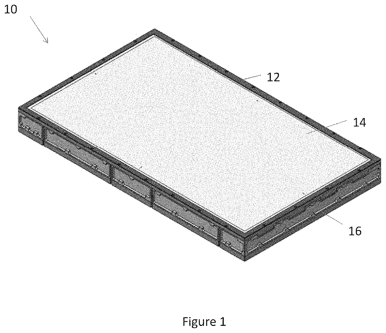
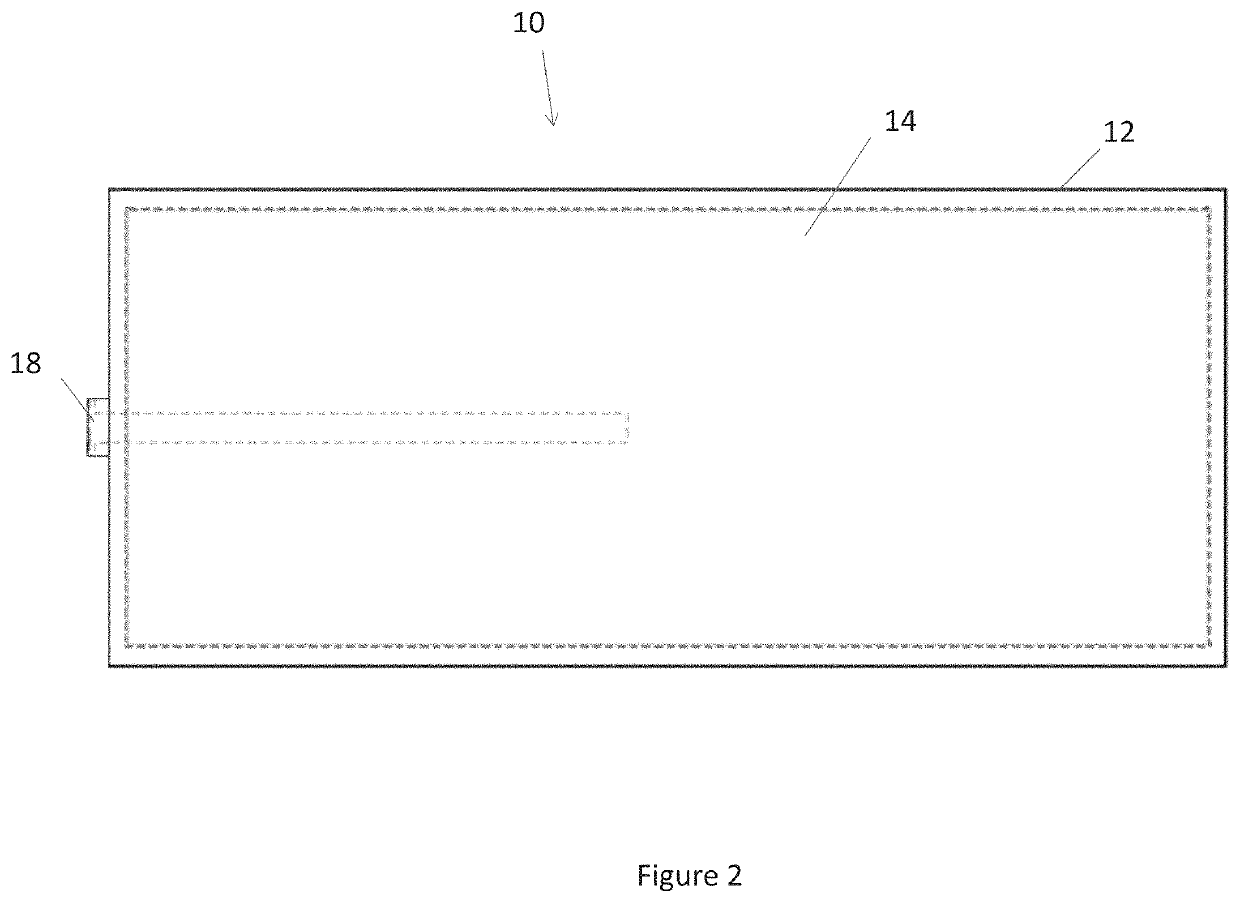
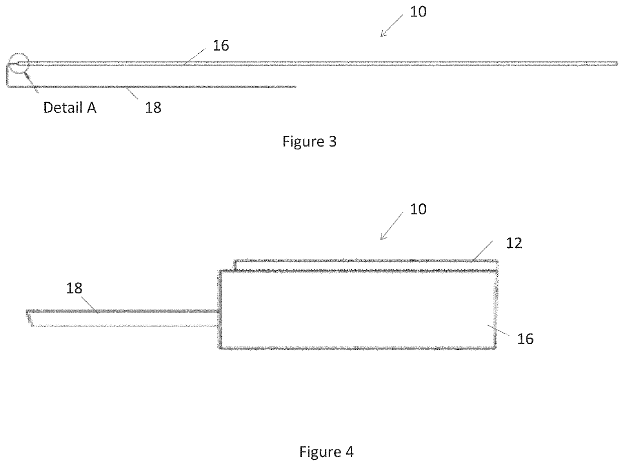
[0021]The invention is described more fully hereinafter with reference to the accompanying drawings, in which exemplary embodiments of the invention are shown. This invention may, however, be embodied in many different forms and should not be construed as limited to the exemplary embodiments set forth herein. Rather, these embodiments are provided so that this disclosure will be thorough and complete, and will fully convey the scope of the invention to those skilled in the art. In the drawings, the size and relative sizes of layers and regions may be exaggerated for clarity.

[0022]The terminology used herein is for the purpose of describing particular embodiments only and is not intended to be limiting of the invention. As used herein, the singular forms “a”, “an” and “the” are intended to include the plural forms as well, unless the context clearly indicates otherwise. It will be further understood that the terms “comprises” and / or “comprising,” when used in this specification, spe...


PUM


Abstract

An electronic display assembly includes a display layer for displaying an image, a projected capacitive touch panel with touch input areas, each of which are independently operable and configured to receive touch input from a user. Input / output devices are electrically connected with the display layer touch panel. Software instructions, when executed, configure one or more processors to automatically begin utilizing a remaining operable input / output device if one of said input / output devices is rendered inoperable.

Description

CROSS-REFERENCE TO RELATED APPLICATIONS[0001]This application is a continuation of U.S. application Ser. No. 14 / 876,393 filed Oct. 6, 2015, the disclosures of which are hereby incorporated by reference as if fully restated.TECHNICAL FIELD[0002]Embodiments of the present invention generally relate touch screen displays.BACKGROUND AND SUMMARY OF THE INVENTION[0003]Electronic touch panel displays are used in many commercial applications including ATMs, automobiles, informational displays, personal computers, cell phones, and the like. Such displays are advantageous as the content may be easily changed and the displays are interactive. For many applications having an electronic touch panel display is desirable, but requirements or needs for redundancy have prevented the use of such displays.[0004]Examples of such applications include, but are not limited to, commercial aviation, space flight, and military applications, where redundancy measures are demanded to ensure continued performan...

Claims


Application Information

Patent Timeline
Patent Type & Authority Patents(United States)
IPC IPC(8): G06F3/041G06F1/16G06F3/0488G06F3/044
CPCG06F3/04166G06F1/1656G06F3/0444G06F3/04886G06F2203/04107G06F2203/04803G06F3/045
Inventor MAHDI, KEN
Owner MERCURY MISSION SYST LLC
Why Eureka
Try Eureka