
Wireless power transmitting device and method for supplying wireless power thereof

a wireless power and transmitting device technology, applied in the direction of inductances, instruments, transportation and packaging, etc., can solve the problems of wasting wireless power efficiency, affecting the efficiency of wireless power transmission and receiving, and affecting so as to achieve maximum wireless power efficiency, maximize the effect of wireless power and/or improve the efficiency of wireless power

Active Publication Date: 2021-11-16
SAMSUNG ELECTRONICS CO LTD
View PDF23 Cites 0 Cited by
  • Summary
  • Abstract
  • Description
  • Claims
  • Application Information

AI Technical Summary

Benefits of technology

The patent text describes a method to improve the efficiency of wireless power transfer between two electronic devices. By aligning the wireless power transmission coil of the first device with the wireless power reception coil of the second device, the method reduces wasted power and prevents interference. The efficiency of wireless power can be indicated through a simple display, making it easy for users to align the devices for maximum efficiency. The technical effect of the patent is to optimize wireless power transfer and reduce energy waste.

Problems solved by technology

Further, even if the distance between the wireless power transmitting device and the wireless power receiving device is fixed, impedance of a load may be changed according to an ON / OFF state of the functional part of the electronic device connected to the wireless power receiving device to cause a difference in efficiency of wireless power being transmitted and received.
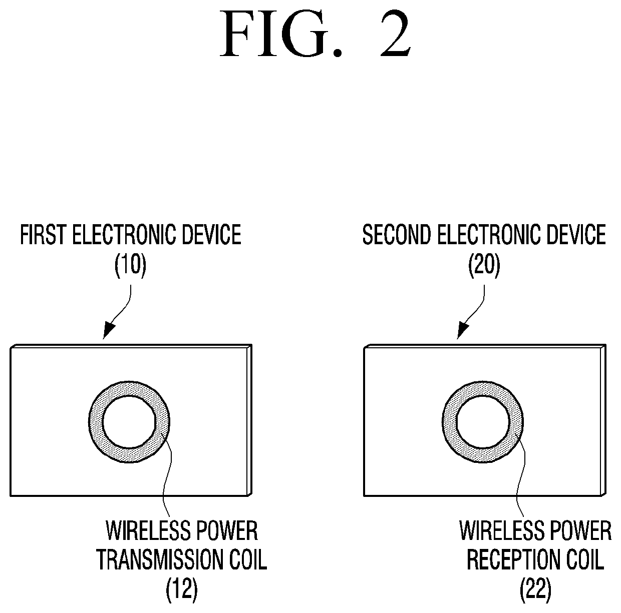
In addition, if a wireless power transmission coil of the wireless power transmitting device and a wireless power reception coil of the wireless power receiving device are not aligned correctly, the efficiency of wireless power may be deteriorated.
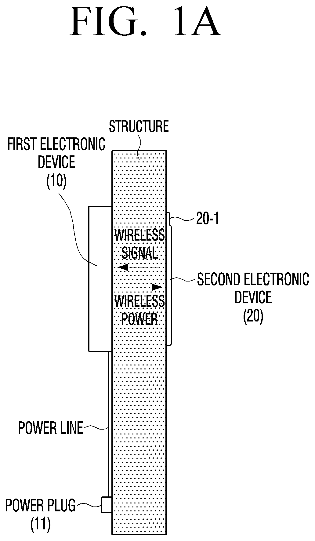
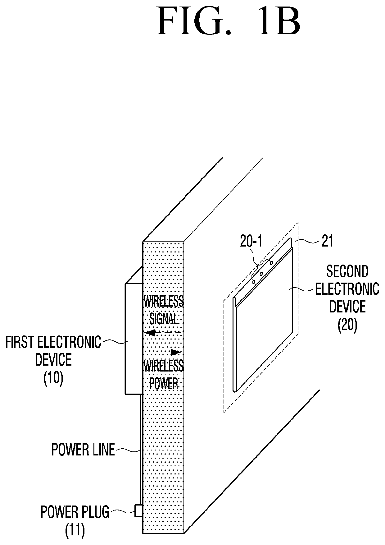
However, if a structure (e.g., a wall, etc.) exists between the wireless power transmitting device and the wireless power receiving device, it may be difficult for a user to arrange the wireless power transmitting device and the wireless power receiving device to maximize wireless power efficiency.
In particular, if the wireless power transmitting device and the wireless power receiving device are not properly arranged, wireless efficiency may be wasted and electromagnetic interference (EMI) may occur due to a leakage magnetic field.

Method used


Image

  • Wireless power transmitting device and method for supplying wireless power thereof
  • Wireless power transmitting device and method for supplying wireless power thereof
  • Wireless power transmitting device and method for supplying wireless power thereof

Examples


Embodiment Construction

[0033]Various example embodiments of the present disclosure may be diversely modified. Accordingly, various example embodiments are illustrated in the drawings and are described in greater detail in the disclosure. However, it is to be understood that the present disclosure is not limited to a specific example embodiment, and includes all modifications, equivalents, and substitutions without departing from the scope and spirit of the present disclosure. Also, well-known functions or constructions may not described in detail where they would obscure the disclosure with unnecessary detail.

[0034]It should be appreciated that various example embodiments of the disclosure and the terms used therein are not intended to limit the technological features set forth herein to particular embodiments and include various changes, equivalents, or replacements for a corresponding embodiment. With regard to the description of the drawings, similar reference numerals may be used to refer to similar o...


PUM


Abstract

A wireless power transmitting device is disclosed. The wireless power transmitting device includes a first communicator comprising communication circuitry configured to communicate with a wireless power receiving device, a wireless power transmitter configured to supply wireless power to the wireless power receiving device, and a first controller configured to control the wireless power transmitter to supply initiating power for obtaining wireless power efficiency to the wireless power receiving device and to control the wireless power transmitter to supply driving power for driving an electronic device including the wireless power receiving device to the wireless power receiving device based on the wireless power efficiency being a predetermined value or greater based on information received from the wireless power receiving device through the first communicator.

Description

CROSS-REFERENCE TO RELATED APPLICATION[0001]This application is based on and claims priority under 35 U.S.C. § 119 to Korean Patent Application No. 10-2019-0044443, filed on Apr. 16, 2019, in the Korean Intellectual Property Office, the disclosure of which is incorporated by reference herein in its entirety.BACKGROUNDField[0002]The disclosure relates to a wireless power transmitting device and a method for supplying power to an electronic device using the same.Description of Related Art[0003]A wireless power system may include a wireless power transmitting device that wirelessly transmits power for driving an electronic device and a wireless power receiving device that receives wireless power from the wireless power transmitting device. For example, wireless power may be supplied from the wireless power transmitting device connected to a power source to the wireless power receiving device connected to a functional part of an electronic device.[0004]There may be a difference in effic...

Claims


Application Information

Patent Timeline
Patent Type & Authority Patents(United States)
IPC IPC(8): H02J5/00H02J7/00H02J50/10H02J50/40H02J50/80H02J50/70G08B21/02
CPCH02J50/80G08B21/023G08B21/0219G08B21/0277H02J50/10H02J50/70H02J50/12H02J50/90H01F38/14H02J50/005
Inventor CHOI, YOUNGHOKANG, JEONGIL
Owner SAMSUNG ELECTRONICS CO LTD
Learn More