Check patentability & draft patents in minutes with Patsnap Eureka AI!

Four-way valve

a valve and valve body technology, applied in the field of four-way valves, can solve the problems of heat loss, large diameter, relative large size, etc., and achieve the effects of reducing turbulence intensity, reducing flow loss of refrigerant, and minimizing pressure drop during flow

Active Publication Date: 2021-11-23
LG ELECTRONICS INC
View PDF22 Cites 0 Cited by
  • Summary
  • Abstract
  • Description
  • Claims
  • Application Information

AI Technical Summary

Benefits of technology

The present invention provides a four-way valve that reduces the pressure drop of the refrigerant and minimizes the rotation angle of the motor. This is achieved by coupling the motor shaft to a switching guide that matches the central axis of the low pressure pipe hole. By doing so, the motor rotates in both directions, which reduces the rotation angle and allows for a smaller motor size.

Problems solved by technology

Meanwhile, in recent years, development of an electric vehicle that uses electric power as a power source to replace a car using oil as a power source causing pollution.
For this reason, miniaturization of the devices installed in the engine room is a very important objective and technical problem in a technical field of the electric vehicle.
However, the four-way valve according to the related art has a relatively large size, which is inappropriate to be installed in the engine room having the limited volume.
Specifically, the four-way valve according to the related art has a problem in that four ports for guiding a flow of the refrigerant are all formed on the same surface, thus having a relatively large diameter.
This causes a problem in that heat loss occurs due to heat transfer between the high temperature and high pressure refrigerant and the low temperature and low pressure refrigerant.
In addition, since the four-way valve according to the related art provides a flow path of the ‘U’ shape in which a flow direction from an inflow of the refrigerant to an outflow of the refrigerant is changed by 180 degrees, a turbulence intensity is relatively large, making a large flow loss.

Method used


Image

  • Four-way valve
  • Four-way valve
  • Four-way valve

Examples


Embodiment Construction

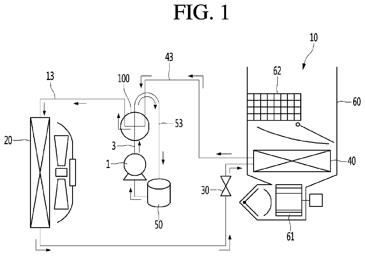
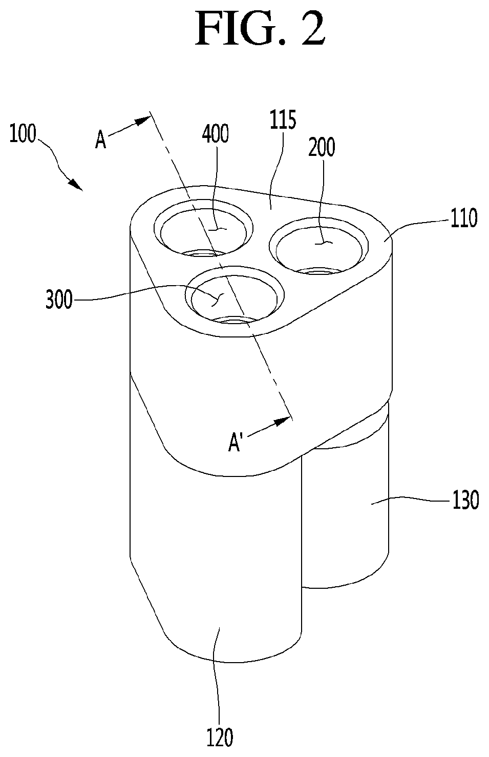
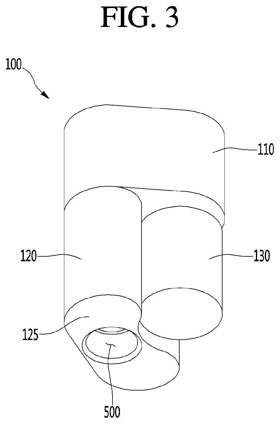
[0050]Reference will now be made in detail to the exemplary embodiments of the present disclosure, examples of which are illustrated in the accompanying drawings. Wherever possible, the same reference numbers will be used throughout the drawings to refer to the same or like parts.

[0051]Reference will now be made in detail to the embodiments of the present disclosure, examples of which are illustrated in the accompanying drawings.

[0052]In the following detailed description of the preferred embodiments, reference is made to the accompanying drawings that form a part hereof, and in which is shown by way of illustration specific preferred embodiments in which the invention may be practiced. These embodiments are described in sufficient detail to enable those skilled in the art to practice the invention, and it is understood that other embodiments may be utilized and that logical structural, mechanical, electrical, and chemical changes may be made without departing from the spirit or sco...


PUM


Abstract

Disclosed is a four-way valve including a housing having a refrigerant filling chamber formed therein, a high pressure pipe hole formed on a bottom surface of the housing and coupled to a high pressure pipe through which refrigerant discharged from the compressor flows, a first pipe hole formed on an upper surface of the housing and coupled to a first pipe extending to a first heat exchanger, a second pipe hole formed on the upper surface of the housing and coupled to a second pipe extending to a second heat exchanger, a low pressure pipe hole formed on the upper surface of the housing and configured to allow the refrigerant to be collected to the compressor, and a switching guide configured to rotate to allow the low pressure pipe hole to selectively communicate with the first pipe hole or the second pipe hole.

Description

CROSS-REFERENCE TO RELATED APPLICATIONS[0001]The present application claims priority under 35 U.S.C. 119 and 35 U.S.C. 365 to Korean Patent Application No. 10-2019-0039732, filed in Korea on Apr. 4, 2019, which is hereby incorporated by reference in its entirety.BACKGROUNDField of the Invention[0002]The present disclosure relates to a four-way valve and, more particularly, to a four-way valve for switching a refrigerant flow path.Discussion of the Related Art[0003]In general, a heating and cooling device for cooling or heating using a phase change of a refrigerant includes an indoor unit having an indoor heat exchanger and an outdoor unit having an outdoor heat exchanger.[0004]During cooling, the refrigerant discharged from the compressor is supplied to an outdoor heat exchanger that performs a function of a condenser, and then heat-exchanged, while passing through an indoor heat exchanger that performs a function of an evaporator to cool a room (or indoor area). In addition, during...

Claims


Application Information

Patent Timeline
Patent Type & Authority Patents(United States)
IPC IPC(8): B60H1/00F16K11/074F16K31/04
CPCB60H1/00485F16K11/074F16K31/041B60H2001/00935F25B2313/02741F15B2013/0413F16K31/04F16K31/047F16K11/072B60Y2200/91F25B41/26Y02B30/00
Inventor LEE, JOOSEONGCHOI, INHOKIM, KYUNGHWAN
Owner LG ELECTRONICS INC
Features
  • R&D
  • Intellectual Property
  • Life Sciences
  • Materials
  • Tech Scout
  • Unparalleled Data Quality
  • Higher Quality Content
  • 60% Fewer Hallucinations
Learn More