Systems and methods for installing flush mounted electrical devices

a technology for flush mounting and electrical devices, applied in the direction of electrical cable installation, electrical apparatus, cable installation apparatus, etc., can solve the problems of unsightly openings on the wall, mounting through a difficult process involving expensive materials, large and expensive gypsum, etc., and achieve the effect of improving the installation process

Active Publication Date: 2021-11-23
GUTHMILLER MARTY
View PDF42 Cites 2 Cited by
  • Summary
  • Abstract
  • Description
  • Claims
  • Application Information

AI Technical Summary

Benefits of technology

[0045]It is another (and optionally independent) object of the invention to provide a flush-mounting system for electrical and other devices and installation methods that are easier than existing methods that attempt to achieve a flush-mounted look.
[0047]It is another (and optionally independent) object of the invention to provide a flush-mounting system for electrical and other devices that is affordable.
[0054]It is another (and optionally independent) object of the invention for faceplates to be sturdy, flush, and easy to install / remove.
[0055]It is another (and optionally independent) object to provide efficient flush mounting systems that are made of plastic and can be cost-effectively manufactured with computerized three-dimensional printing systems.
[0056]It is another (and optionally independent) object to provide flush mounting systems that can be easily adapted for a wide range of electrical devices, such as computers, cameras, switches, outlets and other components that typically connect to electrical, communication and component boxes mounted behind walls.
[0057]It is another (and optionally independent) object to provide flush mounting systems and methods that provide an attractive flush finish and can be installed and finished with minimal additional labor and materials as compared to previously existing systems.

Problems solved by technology

Usually, the wall includes unsightly openings to access the box and its associated contents and electrical wiring.
One flaw with the TRUFIG system is that it is mounted though a difficult process involving expensive materials.
The TRUFIG system includes a large and expensive gypsum “mounting platform” that is screwed into the studs of the wall, fitted with the drywall, and mudded at the same time drywall is mudded.
Alternatively, the existing studs must be modified or relocated, which is often impractical.
The above process is complex, labor intensive and time consuming.
An additional problem with the TRUFIG system is that its mounting platform requires extra mesh tape during drywall mudding.
However, this bracket does not include any pores or holes to assist with mud adhesion to the bracket.
Again, this process is time consuming and labor intensive, and adds further cost to the process.
Another problem with TRUFIG is that the electrical outlet or other device installed in the box behind the wall cannot be wired and installed until after drywall installation and mudding is completed.
With the TRUFIG system, the steps of mounting and wiring the electrical equipment and sub plate cannot be completed before mudding unless the installer is willing to expose the installed electrical equipment and subplate to the mud and / or dust during mudding and sanding process.
The sanding shield is designed to fit in place of the sub plate, and it will not fit over an installed sub plate and electrical device.
TRUFIG provides no mechanism for protecting an already installed subplate and electrical device during mudding.
Yet another problem with the TRUFIG sub plate is that the screws locking it into place must be adjusted to properly align the fascia plate to be “flush” with the wall.
This process adds still further time and labor to complete the installation.
In addition, the TRUFIG system is very expensive compared to standard wall mounted electrical systems (with retail prices starting at $135 for the mounting platform alone, and additional costs for the fascia plates and other tools).
TRUFIG's use of neodymium magnets to attach the fascia plates is certainly one of the main factors driving up the cost of the product.
If the sub plate and electrical equipment is installed before, it cannot be covered by the sanding shield, and it will be exposed to and possibly damaged by the mud.

Method used


Image

  • Systems and methods for installing flush mounted electrical devices
  • Systems and methods for installing flush mounted electrical devices
  • Systems and methods for installing flush mounted electrical devices

Examples


Embodiment Construction

[0352]In the following description, and for the purposes of explanation, numerous specific details are set forth in order to provide a thorough understanding of the various aspects of the invention. It will be understood, however, by those skilled in the relevant arts, that the present invention may be practiced without these specific details. In other instances, known structures and devices are shown or discussed more generally in order to avoid obscuring the invention. In many cases, a description of the operation is sufficient to enable one to implement the various forms of the invention, particularly when the operation is to be implemented in software. It should be noted that there are many different and alternative configurations, devices and technologies to which the disclosed inventions may be applied. The full scope of the inventions is not limited to the objects described above or the specific examples that are described below.

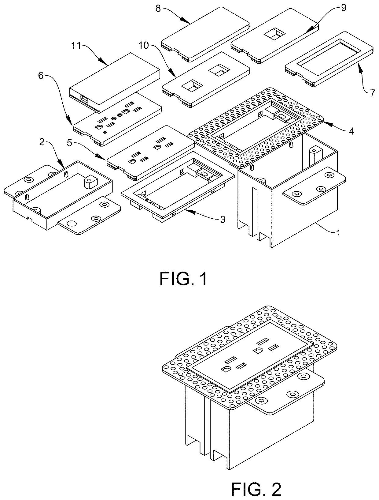
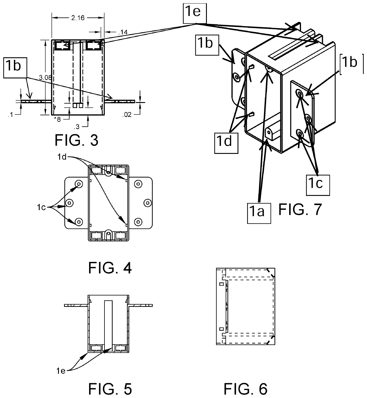
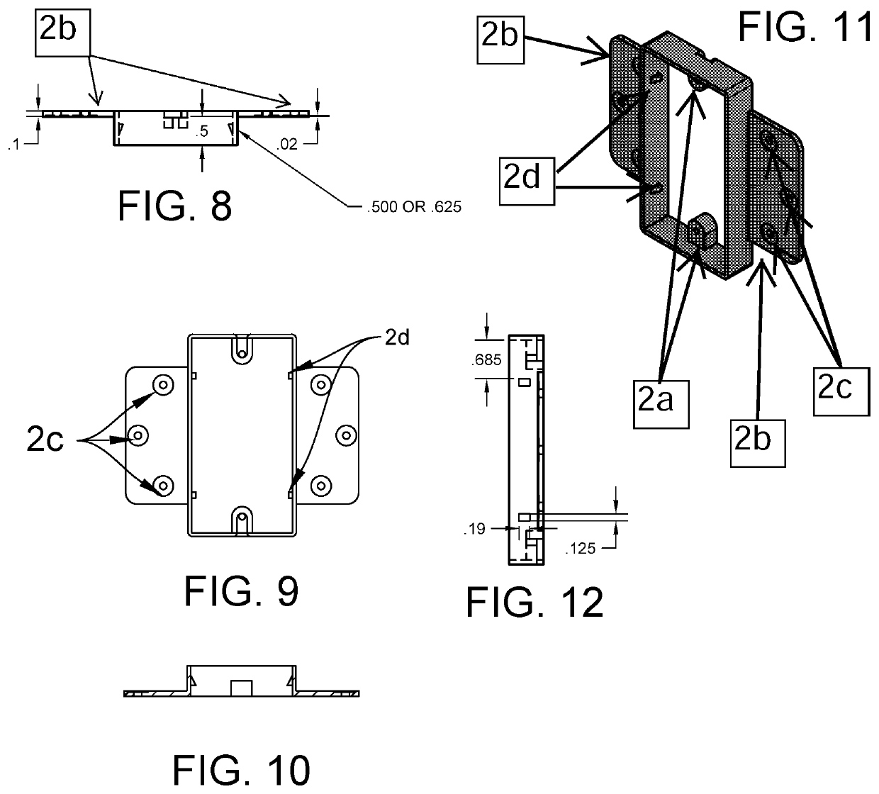
[0353]The figures show parts for several forms ...


PUM


Abstract

Systems and methods for mounting electrical devices such that they appear “flush” with a finished wall. The systems include specialized back boxes, mud rings, faceplates, and other tools that are installed and used during the mounting process. The mounting process includes a specific series of steps that take place during construction and wall finishing, including that mud or other finishing material is used to both “hide” the mounting system and lock it into place The systems and methods allow for full usage of existing electrical devices such as electric outlets, light switches, and USB connectors, with an improved visual appearance over existing electrical plates that sit on top of the wall.

Description

CROSS REFERENCE TO RELATED APPLICATIONS[0001]This application is a continuation of Provisional Application No. 62 / 833,954, Filed Apr. 15, 2019, which is herein incorporated by reference.BACKGROUND1. Field of the Invention[0002]For years, homes and business have made use of electrical devices that are mounted to interior walls. For example, virtually all modern homes and businesses use light switches, electrical outlets, TV jacks, computer jacks, security cameras, motion detectors and many other wall mounted devices. Typically, such devices connect to power, data or communication sources in a box (such a switch, outlet, cable or other common box) mounted to studs behind the wall. Usually, the wall includes unsightly openings to access the box and its associated contents and electrical wiring. A corresponding cover plate (such as a switch, outlet, cable or other plate) covers the unsightly opening in the drywall or plaster. Typically, the cover plate is slightly larger than the access...

Claims


Application Information

Patent Timeline
Patent Type & Authority Patents(United States)
IPC IPC(8): H02G3/08H02G3/12H02G1/00H02G3/14
CPCH02G3/12H02G1/00H02G3/083H02G3/14H02G3/123H02G3/18
Inventor GUTHMILLER, MARTY
Owner GUTHMILLER MARTY
Why Eureka
Try Eureka