
Electric vehicle braking system, method, controller and computer program product

a technology for electric vehicles and brake systems, applied in brake systems, electrodynamic brake systems, electric vehicles, etc., can solve the problems of inefficient energy generation, non-optimal energy generation, and inefficient energy generation, and achieve the effect of maximizing energy generation

Active Publication Date: 2021-12-07
JAGUAR LAND ROVER LTD
View PDF33 Cites 1 Cited by
  • Summary
  • Abstract
  • Description
  • Claims
  • Application Information

AI Technical Summary

Benefits of technology

The patent describes a braking system for vehicles that can adjust its braking force to improve energy generation and range. The system uses data from vehicle sensors to determine the optimum distribution of braking force to prevent over-steering or under-steering, and to maximize energy recovery during braking events. The system can also retard the vehicle partially using hydraulic braking in response to insufficient regenerative braking. Overall, the system improves the vehicle's stability and range while reducing emissions.

Problems solved by technology

However, during regenerative braking, the process is reversed and the shaft is decelerated by resistance in using the electric machine as a generator to convert the mechanical energy of the shaft rotation into electrical energy.
In this way, the energy recovered during regenerative braking is not optimised since during the life of the vehicle, various components, such as the electric machines, may become temporarily de-rated, leading to non-optimal energy generation.
For instance, a front biased brake force distribution where the front generator is de-rated, would lead to inefficient energy generation.
However, varying the brake force distribution between the front and rear axles may cause problems with vehicle stability.

Method used


Image

  • Electric vehicle braking system, method, controller and computer program product
  • Electric vehicle braking system, method, controller and computer program product
  • Electric vehicle braking system, method, controller and computer program product

Examples


Embodiment Construction

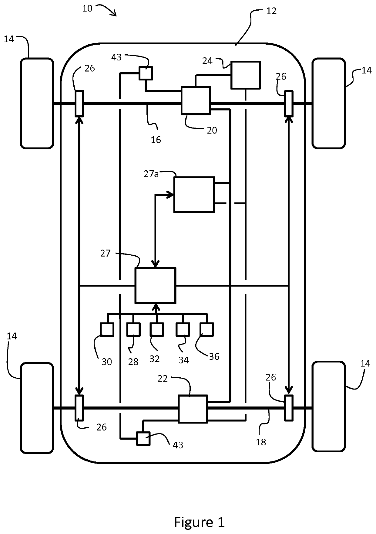
[0041]With reference to FIG. 1, a vehicle 10 includes a body 12 driven by a set of wheels 14. The wheels 14 support the body on respective front and rear axles 16, 18.

[0042]The vehicle in this embodiment is an electric vehicle, though this invention is also applicable to hybrid electric vehicles. The electric vehicle 10 includes a front machine 20 on the front axle 16 and a rear machine 22 on the rear axle 18. Alternatively, the vehicle 10 may include more than one machine on each axle 16, 18, for instance one machine on each side shaft, or expressed differently, one machine per wheel. Each machine is operable to act as a motor for converting electrical energy into kinetic energy for powering the respective axle. In addition, each machine is operable to act as a generator for converting kinetic energy recovered during a braking event into electrical energy. The electrical energy is stored in a battery 24.

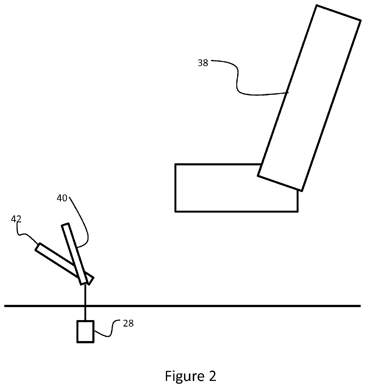
[0043]The vehicle 10 also includes hydraulic braking provisions in the form of ...


PUM


Abstract

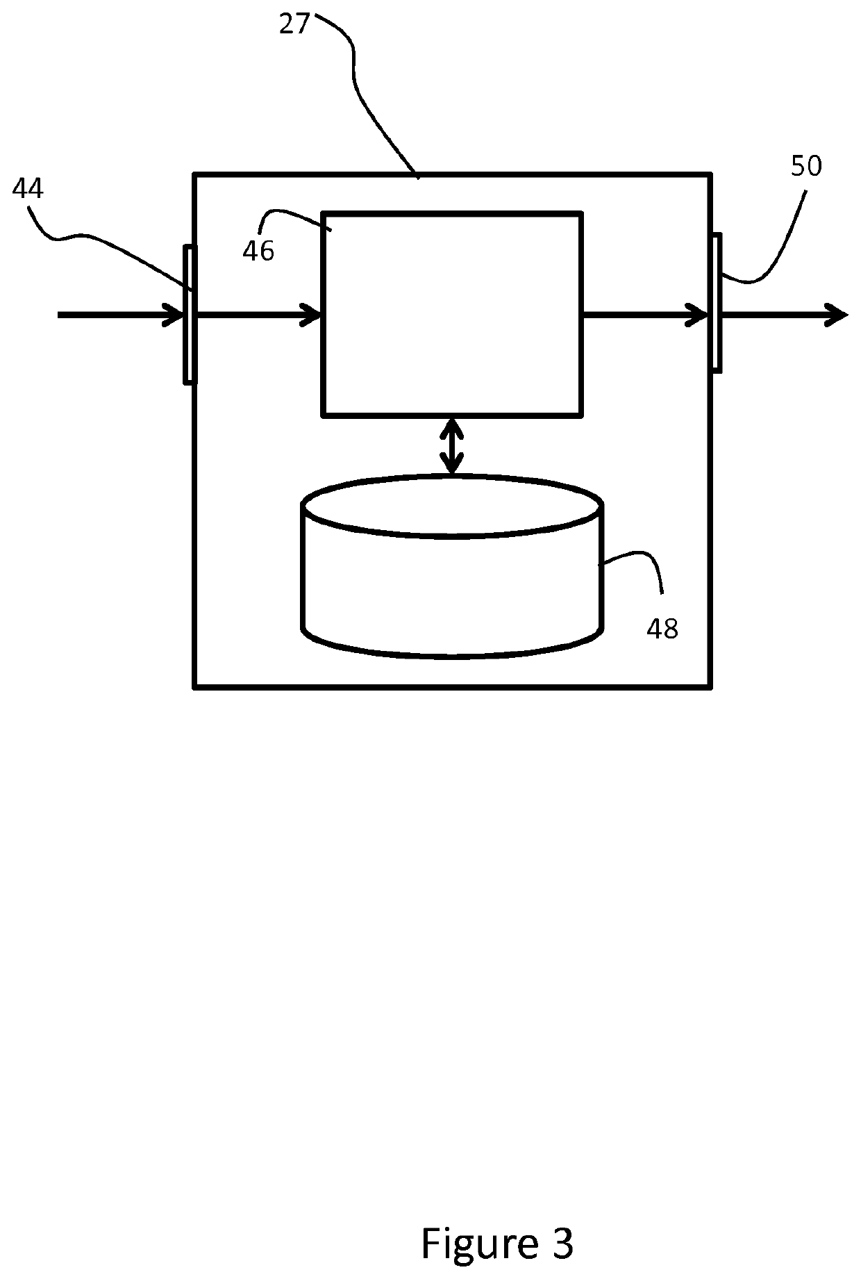
The present invention relates to a controller (27) for a braking system for a vehicle (10). The braking system has an independent generator (20, 22) on respective front and rear axles (16, 18). The controller (27) comprises an input (44) arranged to monitor a vehicle condition and an operating condition of the generators (20, 22). The controller (27) also comprises a processing means (46) arranged to determine a brake force distribution range between the front and rear axles (16, 18) based on the vehicle condition, and in response to a braking demand and the operating condition of the generators (20, 22), calculate a brake force distribution within the brake force distribution range. In addition, the controller (27) comprises an output (50) arranged to control the generators in accordance with the calculated brake force distribution.

Description

RELATED APPLICATIONS[0001]This application is a 35 U.S.C. § 371 national stage application of PCT Application No. PCT / EP2016 / 071075, filed on Sep. 7, 2016, which claims priority from Great Britain Patent Application No. GB1515813.2, filed on Sep. 7, 2015, the contents of which are incorporated herein by reference in their entireties. The above-referenced PCT International Application was published in the English language as International Publication No. WO 2017 / 042209 A1 on Mar. 16, 2017.TECHNICAL FIELD[0002]The invention relates to a regenerative braking system and more particularly, but not exclusive, to those regenerative braking systems of an electric or hybrid electric vehicle having an independent generator on each axle. Aspects of the invention relate to a controller for a braking system, a braking system, a vehicle, and a method of operating a braking system of a vehicle.BACKGROUND[0003]A vehicle can be decelerated, or retarded, using a braking system. Typically a braking sy...

Claims


Application Information

Patent Timeline
Patent Type & Authority Patents(United States)
IPC IPC(8): B60L7/26B60T8/1766B60T8/172B60T8/1755B60T8/30B60T8/32B60T8/58B60L7/18B60L15/20
CPCB60L7/26B60L7/18B60L15/2009B60T8/172B60T8/1766B60T8/17551B60T8/17552B60T8/30B60T8/3205B60T8/58B60T2210/12B60T2220/04B60T2250/03B60T2270/60B60T2270/604B60T2270/613Y02T10/64Y02T10/72B60T8/17B60W10/08B60W10/184
Inventor SATTERTHWAITE, ANTHONYHANCOCK, MATTHEWHEGARTY, SIMONGODLEWSKI, NICOLASISMAIL, ZAHIR
Owner JAGUAR LAND ROVER LTD
Learn More