
Combination padlock with anti-picking and decode mechanism

a technology of decoding mechanism and combination padlock, which is applied in the field of combination padlocks, can solve the problems of limited effect, and achieve the effect of improving the fault gate mechanism

Active Publication Date: 2021-12-14
SUN LOCK COMPANY LIMITED -THE-
View PDF57 Cites 4 Cited by
  • Summary
  • Abstract
  • Description
  • Claims
  • Application Information

AI Technical Summary

Benefits of technology

[0003]An embodiment of the present invention is a padlock that incorporates an improved fault gate mechanism. One such embodiment has nine faulty gates and one true gate. This invention makes the combination mechanism more difficult to pick. The new padlock also has a key mechanism to override the combination mechanism, like many TSA luggage locks. Such locks allow TSA agents to open the lock with an overriding key mechanism. The padlock according to the present invention incorporates another feature; namely, a coupling plate, where one side is an anti-picking mechanism and the reverse side of the coupling plate has a decode function. This means that the key mechanism user can open the lock via key mechanism and also be able to decode the combination code via further explanation below.
[0007]A further embodiment of the present invention is the padlock as described above, wherein when the padlock is in the unlock by combination mode, the fin of each of the plurality of clutches is caused to move into the opening slot of the associated connecting plate by the longitudinal movement of the long-leg, so that the dials cannot turn and thereby preventing accidental change of the lock-open combination code.

Problems solved by technology

Prior art U.S. Pat. No. 5,715,709 has faulty gates, but the effectiveness is limited from a production perspective since there is only one true gate with four faulty gates, which is quite easy for a lock picker to pick.

Method used


Image

  • Combination padlock with anti-picking and decode mechanism
  • Combination padlock with anti-picking and decode mechanism
  • Combination padlock with anti-picking and decode mechanism

Examples


Embodiment Construction

. 1A-23)

[0049]Locked mode (FIG. 1A-12, FIG. 13A-13B, FIG. 16, and FIG. 22-23):

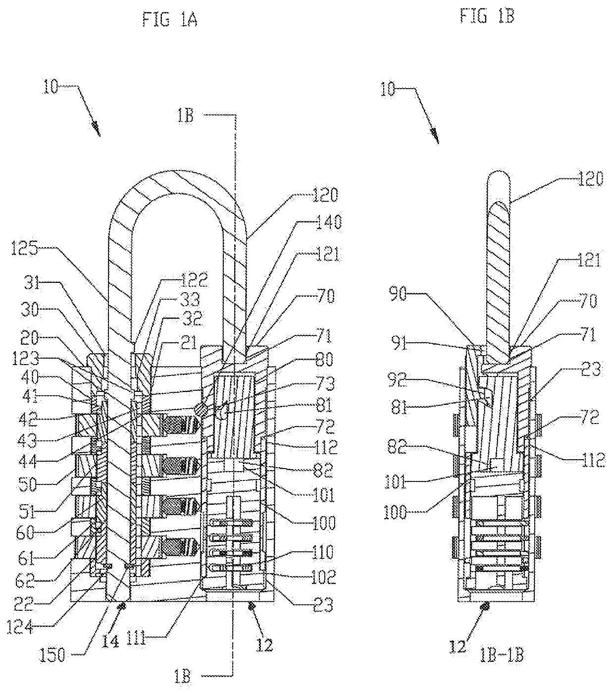
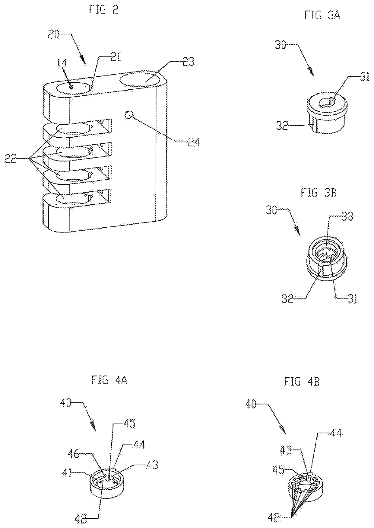
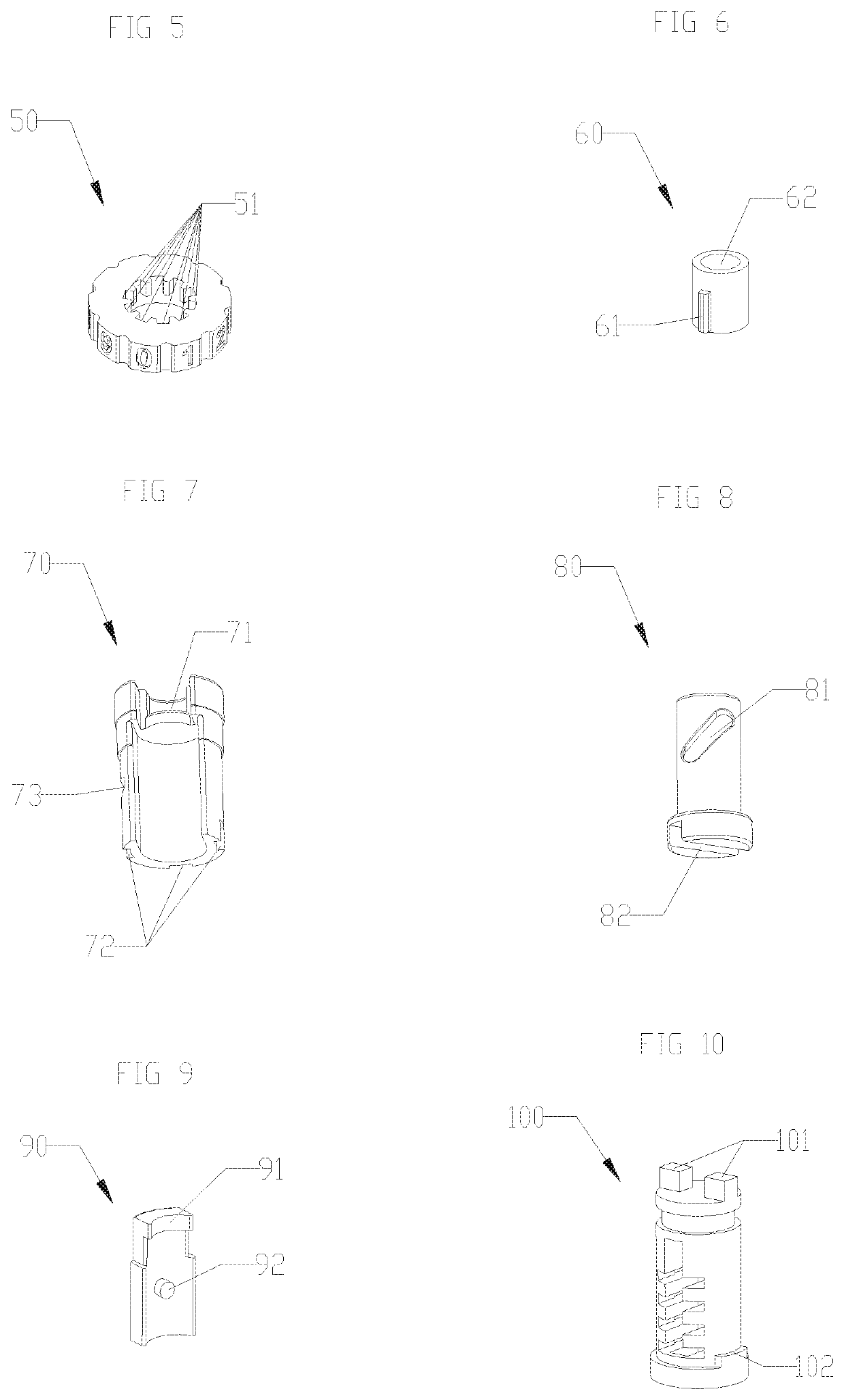
[0050]The padlock 10 contains a shackle 120 where the short-leg-shackle 121 is controlled by key mechanism 12. The key mechanism is positioned in a second bore (cylinder hole) 23 of body 20 (see FIG. 2). The long-leg-shackle 125 is positioned in a first bore 14 of body 20 (see FIG. 2) and is controlled by the combination mechanism. When the lock is in the locked mode, the shackle has no upward movement relative to body 20 so that the short-leg-shackle 121 remains in the locking-hole 71 of the fixed cam 70. Also, since as shown in this embodiment where no correct key 130 has been inserted into cylinder 100 of the key mechanism, the cam remains silent and the blocking plate has no movement which therefore blocks the short-leg-shackle 121 from opening by the key mechanism.

[0051]For the combination locked mode:

[0052]At least one dial 50 is not in the lock open combination and thus will not allow the lock to op...


PUM


Abstract

A padlock comprising a body / housing which contains a fin-catcher and a plate-hole to receive the coupling-plate, a shackle which contains a short-leg and long-leg, so that the short-leg can move away from the locking-hole to control the locking and opening position, a plurality of clutches to prevent the lock from being opened when the dials are not in a lock open by combination code, and a plurality of dials to control the rotational movement of the clutches.

Description

TECHNICAL FIELD[0001]The technical field of the present invention relates to combination padlocks.BACKGROUND OF THE INVENTION[0002]The present invention is a combination padlock with an advanced anti-picking mechanism which is enclosed in a locking body / housing. Prior art U.S. Pat. No. 5,715,709 has faulty gates, but the effectiveness is limited from a production perspective since there is only one true gate with four faulty gates, which is quite easy for a lock picker to pick.SUMMARY OF THE INVENTION[0003]An embodiment of the present invention is a padlock that incorporates an improved fault gate mechanism. One such embodiment has nine faulty gates and one true gate. This invention makes the combination mechanism more difficult to pick. The new padlock also has a key mechanism to override the combination mechanism, like many TSA luggage locks. Such locks allow TSA agents to open the lock with an overriding key mechanism. The padlock according to the present invention incorporates a...

Claims


Application Information

Patent Timeline
Patent Type & Authority Patents(United States)
IPC IPC(8): E05B37/02E05B67/24E05B35/10E05B37/00E05B67/00
CPCE05B37/0034E05B35/105E05B37/002E05B37/0058E05B37/025E05B67/003E05B67/24E05B37/0041
Inventor LAI, KARL
Owner SUN LOCK COMPANY LIMITED -THE-
Learn More