Lighting device with substrate and reflective sheet and display device having lighting device with substrate and reflective sheet

a technology of lighting device and substrate, applied in non-linear optics, instruments, optics, etc., can solve the problems of reducing the reflection efficiency of light in the lighting device (the display device), and achieve the effect of reducing the reflection efficiency of light in the lighting device (the display device) and reducing the reflectivity of light in these areas

Active Publication Date: 2021-12-21
FUNAI ELECTRIC CO LTD
View PDF9 Cites 0 Cited by
  • Summary
  • Abstract
  • Description
  • Claims
  • Application Information

AI Technical Summary

Benefits of technology

[0006]However, in the Patent Literature 1, as the substrate is exposed (no reflective sheet is provided) between the reflective sheet (the inner peripheral edge portions of the through holes) and the other ends of the LED light sources as viewed from the perpendicular direction, the reflectivity of the light in these areas is reduced. Due to this, there is a problem that the reflection efficiency of light in the lighting device (the display device) is reduced.
[0007]This invention has been made to solve the above-mentioned problems, and one object of this invention is to provide a lighting device and a display device capable of suppressing a decrease in the reflection efficiency of light in a lighting device (a display device).

Problems solved by technology

Due to this, there is a problem that the reflection efficiency of light in the lighting device (the display device) is reduced.

Method used


Image

  • Lighting device with substrate and reflective sheet and display device having lighting device with substrate and reflective sheet
  • Lighting device with substrate and reflective sheet and display device having lighting device with substrate and reflective sheet
  • Lighting device with substrate and reflective sheet and display device having lighting device with substrate and reflective sheet

Examples


first embodiment

[0025](Configuration of a Backlight Unit and a Liquid Crystal Television Device)

[0026]Referring to FIGS. 1 to 8, the configuration of a backlight unit 10 and a liquid crystal television device 100 according to a first embodiment of the present invention will be described. The backlight unit 10 and the liquid crystal television device 100 are examples of the “lighting device” and the “display device” of the present disclosure, respectively.

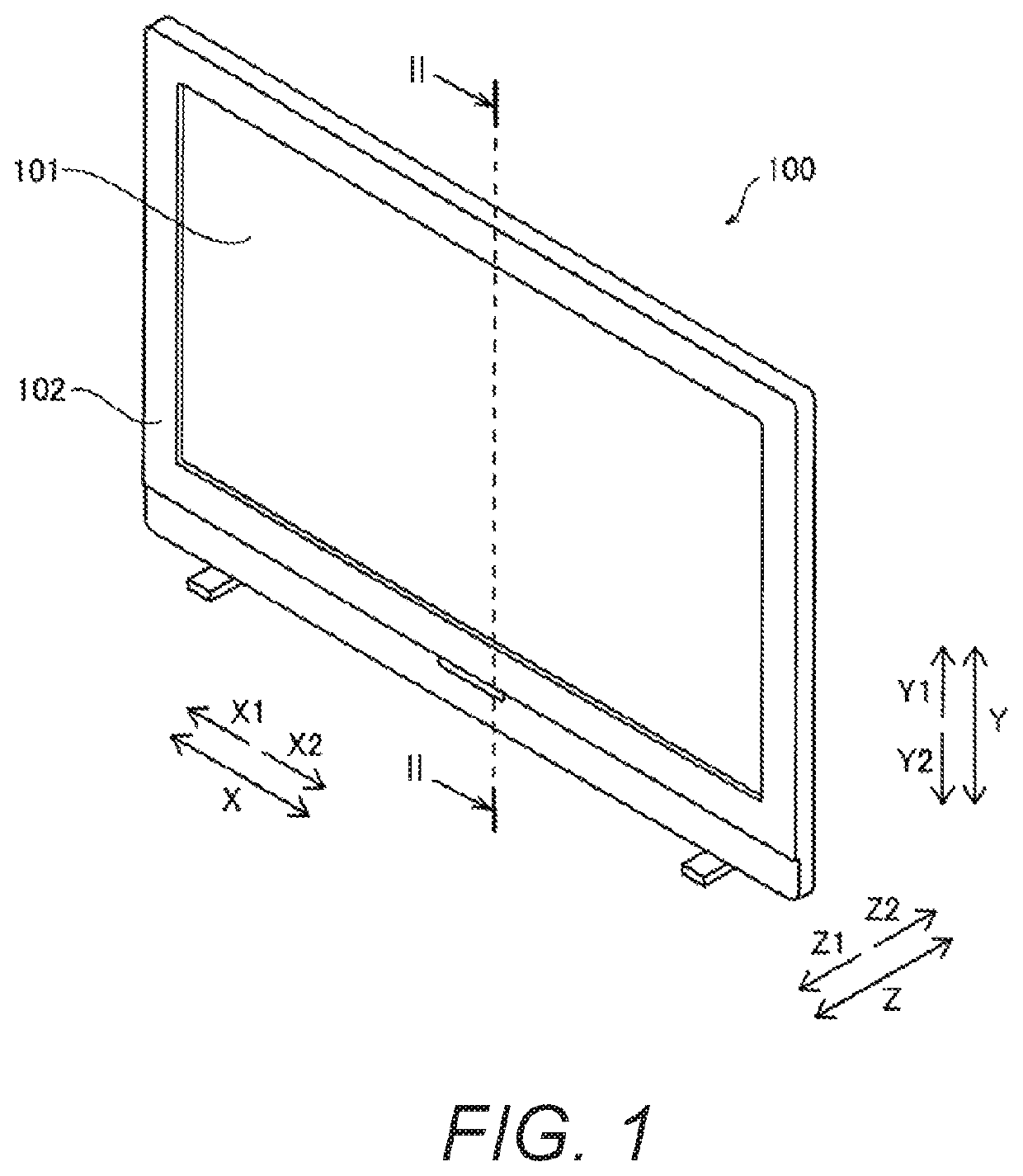
[0027]The liquid crystal television device 100 according to the first embodiment has a display 101 and a housing 102, as shown in FIG. 1.

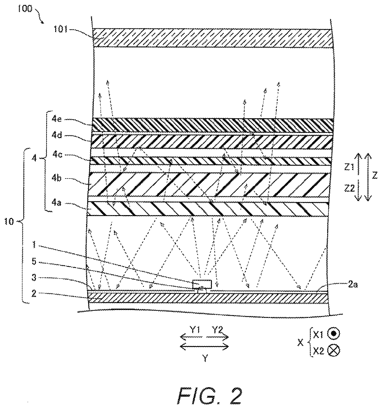
[0028]As shown in FIG. 2, the liquid crystal television device 100 is provided with the backlight unit 10. The backlight unit 10 (the liquid crystal television device 100) comprises an LED 1, a substrate 2, and a reflective sheet 3. The LED 1 emits light onto the display 101. The dashed arrows in FIG. 2 indicate the light path of the light. The LED 1 is an example of the “light source” of the present disclosure.

[0...

second embodiment

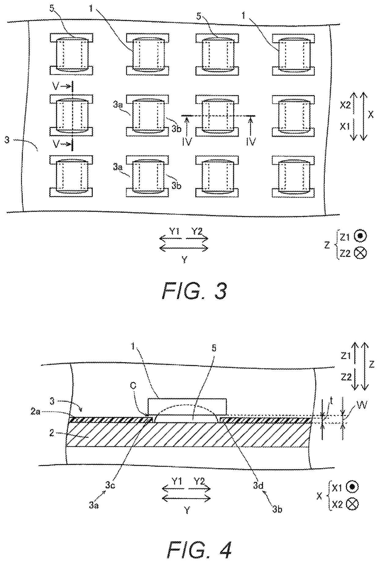
[0058]Referring now to FIGS. 9 to 14, the configuration of a backlight unit 20 and a liquid crystal television device 200 according to a second embodiment will be described. In view of the similarity between the first and second embodiments, the parts of the second embodiment that are identical to or similar to the parts of the first embodiment will be given the same reference numerals as the parts of the first embodiment. Moreover, the descriptions of the parts of the second embodiment that are identical to or similar to the parts of the first embodiment may be omitted for the sake of brevity. In the second embodiment, unlike the first embodiment, out of a first portion 13a of a reflective sheet 13 and a second portion 13b of the reflective sheet 13, only the first portion 13a is inserted into the gap C between the surface 2a of the substrate 2 and the LED 1. Here, the backlight unit 20 and the liquid crystal television device 200 are examples of the “lighting device” and the “disp...

modification examples

[0071]The embodiments disclosed here are illustrative and are not restrictive in all respects. The scope of the invention is indicated by the claims rather than by the description of the embodiments described above, and furthermore includes all modifications (modification examples) within the meaning and scope of the claims and their equivalents.

[0072]For example, in the first and second embodiments above, an example is shown in which the first and second portions 3a and 3b (13a and 13b) of the reflective sheet 3 (13) extends in the Y direction, however, the present invention is not limited to this. For example, the first and second portions 3a and 3b (13a and 13b) of the reflective sheet 3 (13) may extend in the X direction. Specifically, when the gap C between the LED 1 and the surface 2a of the substrate extends from one side of the LED 1 to the other side of the LED 1 in the X direction, the first and second portions 3a and 3b (13a and 13b) of the reflective sheet 3 (13) can be ...


PUM

PropertyMeasurementUnit
lengthaaaaaaaaaa
lengthaaaaaaaaaa
length L11aaaaaaaaaa

Abstract

A lighting device includes a substrate, a light source and a reflective sheet. The light source is fixed relative to a surface of the substrate with a gap therebetween. The reflective sheet includes first and second portions that are separated with respect to each other and are arranged with respect to each other in a first direction. The reflective sheet is configured such that both the first and second portions are inserted into the gap between the light source and the surface of the substrate as viewed from a perpendicular direction, or such that one of the first and second portions extends through the gap between the light source and the surface of the substrate to a vicinity of the other one of the first and second portions that is provided outside of the light source as viewed from the perpendicular direction.

Description

CROSS-REFERENCE TO RELATED APPLICATIONS[0001]This application claims priority to Japanese Patent Application No. 2019-176058 filed on Sep. 26, 2019. The entire disclosure of Japanese Patent Application No. 2019-176058 is hereby incorporated herein by reference.BACKGROUNDField of the Invention[0002]This invention generally relates to a lighting device and a display device. More specifically, the present invention relates to a lighting device and a display device equipped with a reflective sheet that expands and contracts with heat.Background Information[0003]Generally, lighting devices and display devices equipped with a reflective sheet that expands and contracts with heat are known (see International Publication WO 2011 / 152134 (Patent Literature 1), for example).[0004]The Patent Literature 1 discloses a lighting device (a display device) comprising LED light sources, a substrate on which the LED light sources are mounted, and a reflective sheet provided on the substrate. The reflec...

Claims


Application Information

Patent Timeline
Patent Type & Authority Patents(United States)
IPC IPC(8): G02F1/13357
CPCG02F1/133605G02F1/133603G02F2201/54G02F1/133628
Inventor OGAWA, AKIHISAITO, TATSUYA
Owner FUNAI ELECTRIC CO LTD
Why Eureka
Try Eureka