Floating liquid intake

a technology of floating liquid and water intake, which is applied in the direction of sedimentation settling tanks, water cleaning, and separation processes, etc., can solve the problems of affecting the effect of the pump, the sludge that has settled on the floor of the pond or dam is likely to be sucked into the pump, and the tailings matter will be entrained, so as to achieve a greater head

Active Publication Date: 2021-12-28
TURRET IP PTY LTD
View PDF24 Cites 2 Cited by
  • Summary
  • Abstract
  • Description
  • Claims
  • Application Information

AI Technical Summary

Benefits of technology

[0022]A floating liquid intake according to the present invention includes a hollow, annular and buoyant body, which can provide the sole form of buoyancy for the liquid intake. Moreover, the annular body can form a ring from which the upper and lower covers extend and through which each of the annular inlet and the outlet pipe opening extend. The annular body is thus formed in a manner that means that the number of component parts that the liquid intake requires is reduced, compared to the prior art and in particular the applicant's prior floating liquid intake which is the subject of International Patent Application PCT / AU2017 / 050697. The formation of the annular body as a buoyant body has allowed the liquid intake to be developed in a manner that can be more easily commercially manufactured, as the annular body can be manufactured as a single part and the remaining components attached or assembled thereto. The reduction in component parts means the manufacturing time and effort to produce a liquid intake according to the present invention is reduced and the manner in which the annular body can be formed means that the accuracy of manufacture is high and repeatable.
[0052]A submersible pump has advantages in that it can pump to a greater head than a suction pump. Moreover, the liquid intake of the invention can be modified to include a submersible pump without difficulty, so that the application of the liquid intake of the invention can dictate whether the liquid intake operates under suction or with a submersible pump.

Problems solved by technology

A disadvantage with this form of liquid removal system is that the proximity of the pump inlet to the floor of the pond or dam means that the solids that have settled on the floor of the pond or dam are likely to be sucked into the pump inlet if sufficient suction is applied by the pumping system.
A further disadvantage of this system is that the pump inlet is positioned where the water is generally least clean and / or has the greatest amount of suspended solids (being towards the floor of the pond or dam where suspended solids sink towards) and so invariably, tailings matter will be entrained in the water being removed.
In either instance, there can be a detrimental effect for example on the equipment of the pumping system, i.e. clogging filters and pumps and reducing pumping efficiency, while reuse of the water can be affected if it is too highly contaminated with tailings matter.
This can cause obvious issues if the water is being used for irrigation or stock feed.
This can lead to significantly lower pumping performance by affecting the volumetric performance of the pump 17, i.e. the volume of liquid that can be displaced from the pond or dam 10 by the pump 17, but more importantly, the existence of air in the liquid flow through the pump 17 can damage the pump 17 through vibration and there can be a loss of pump performance.
This often means that a significant length of pipe must be used to position the pump inlet at the deepest section of a pond or dam (usually the centre of the pond or dam) thus increasing line losses caused by friction between the water and the pipe and thus reducing pump efficiency.
However, ponds and dams are often shallow at the point at which the pump inlet can be positioned and shallow water presents a difficulty in relation to liquid removal given the needs expressed above to avoid ingress of sediment and solids into the pump inlet and the need to avoid the generation of vortices.
Another issue with systems in which a float is used to suspend the pump inlet at an upper level in the pond or dam is that as the water level reduces in the pond or dam, the suspended pump inlet moves closer to the floor and thus to the sediment and solids that are present at the floor, increasing the likelihood of entraining the sediment and solids through the pump inlet into the pumping system over time.
In these systems, because the suspended pump inlet is suspended at a depth which is at or below the point of critical submergence so the pump inlet is below the liquid surface of the pond or dam, the body of water above the pump inlet is not a usable body in terms of positioning of the pump inlet in clean water and away from the floor of the pond or dam.

Method used


Image

  • Floating liquid intake
  • Floating liquid intake
  • Floating liquid intake

Examples


Embodiment Construction

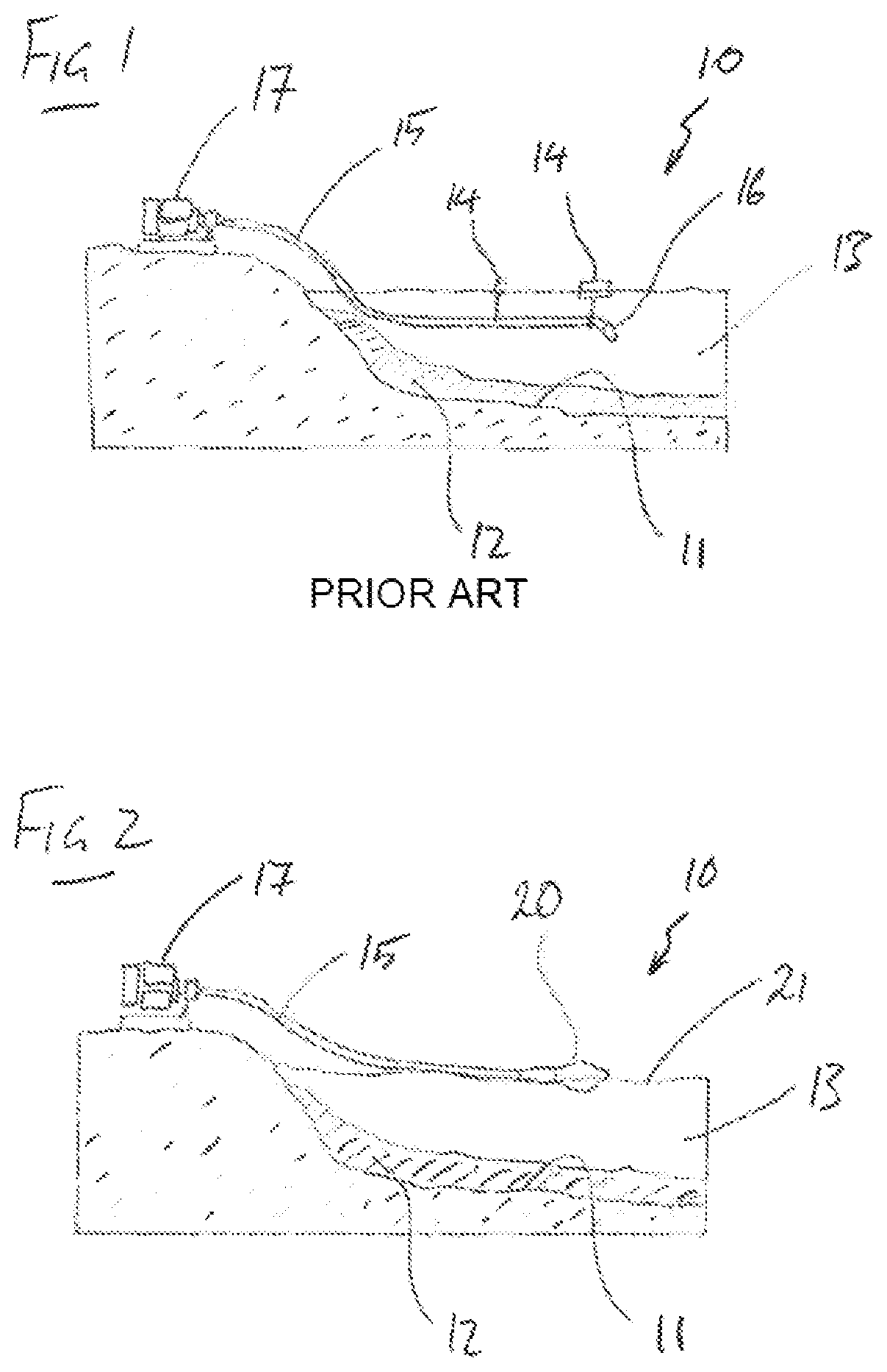
[0067]FIG. 2 is a similar illustration to FIG. 1, but showing schematically, a floating liquid intake 20 according to the present invention in use. FIG. 2 illustrates several of the same features as FIG. 1 and for those features, the same reference numerals are applied. In FIG. 2, it can be seen that the floating liquid intake 20 sits on the surface 21 of the body of water 13 rather than being suspended within the body of water 13 as shown in FIG. 1. It will therefore be appreciated, that the inlet to the liquid intake 20 is much higher than the inlet 16 of FIG. 1. This means that the inlet of the intake 20 of FIG. 2 is much further away from the silt and debris 12 and is located in water which should be cleaner than the water in which the inlet 16 of FIG. 1 is positioned.

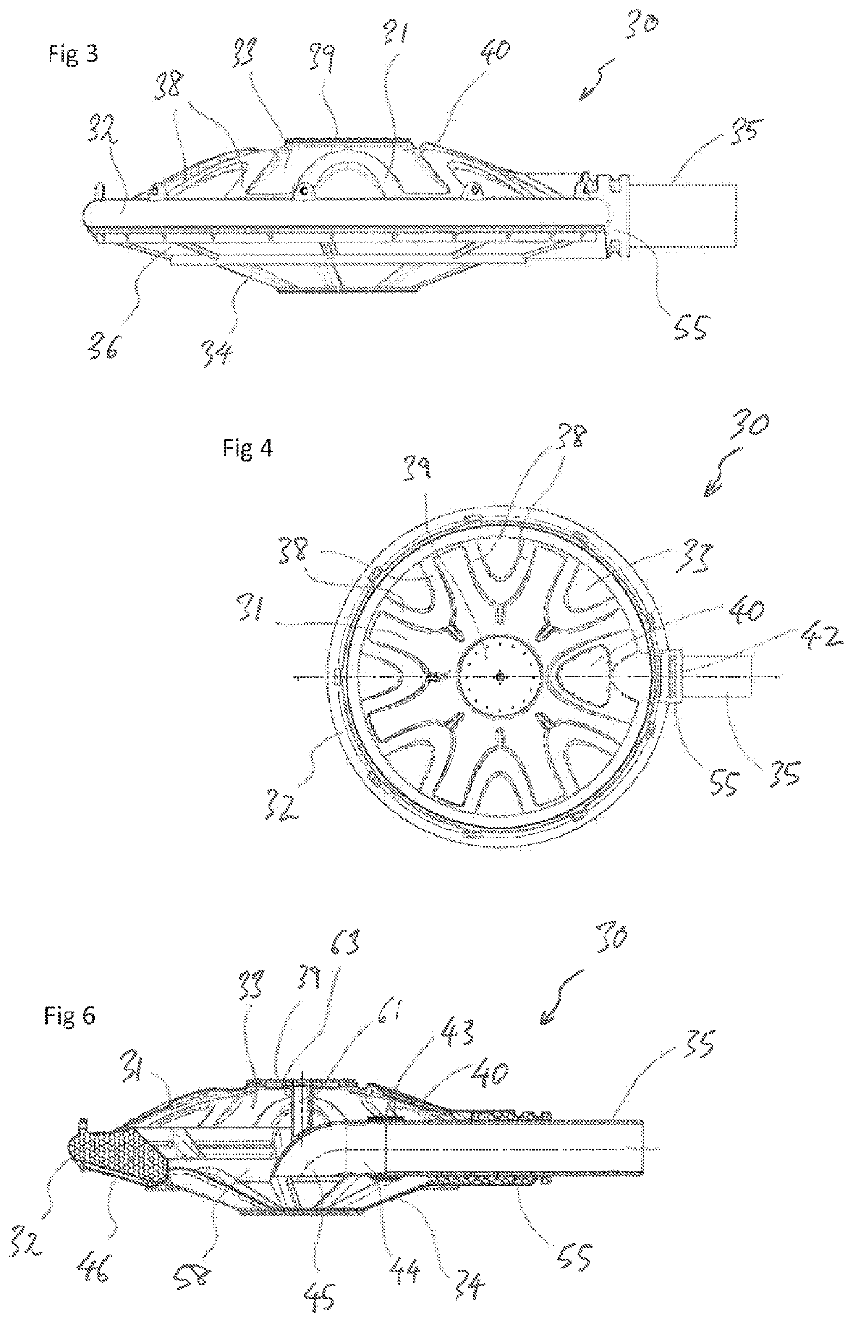
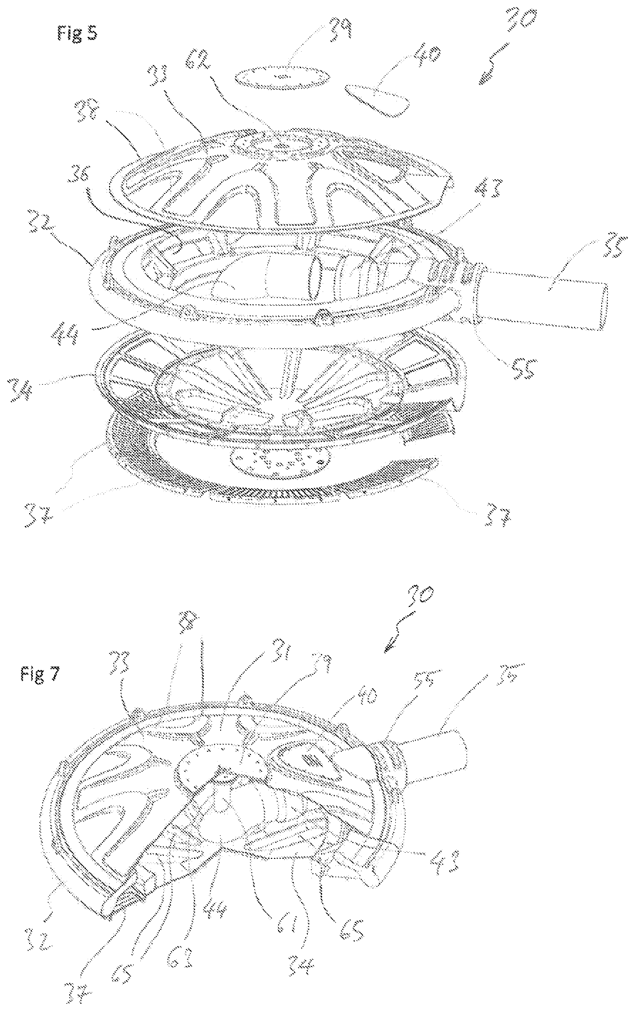
[0068]FIG. 3 is a side view of a liquid intake 30 according to the present invention. The liquid intake 30 can be the same as the liquid intake 20 of FIG. 2. The liquid intake 30 has a housing 31 comprising an annu...


PUM

PropertyMeasurementUnit
depthsaaaaaaaaaa
depthaaaaaaaaaa
diameteraaaaaaaaaa

Abstract

A floating liquid intake for a liquid suction removal system, the liquid intake comprising housing defining an internal cavity. The housing has a hollow and buoyant annular body, an upper cover and a lower cover. The internal cavity is formed between the upper and lower covers. A substantially annular inlet is formed in the annular body for ingress of liquid into the cavity. The annular body has a buoyancy sufficient for the liquid intake to float in a liquid with the annular inlet submerged below the surface of the liquid in which the liquid intake is floating. A pipe extends into the cavity and the pipe includes an inlet that in use is open below the surface of the liquid within the cavity. The pipe extends outside of the cavity for connection to a liquid suction removal system.

Description

PRIORITY CROSS-REFERENCE[0001]The present application is a national stage application, filed under 35 U.S.C. § 371 of International Patent Application No. PCT / AU2018 / 051394, filed 21 Dec. 2018, which claims priority from Australian Provisional Patent Application No. 2017905172 filed 22 Dec. 2017 the contents of which are to be considered to be incorporated into this specification by their reference.TECHNICAL FIELD[0002]The present invention relates to a floating liquid intake for a liquid suction removal system. The present invention has been developed in relation to the removal of water (“dewatering”) from settling ponds, tailing dams, decant ponds, raw water dams, rivers and waterways and it will be convenient to describe the invention in relation to those applications. However, it is to be appreciated that the invention is not limited to those applications.BACKGROUND OF INVENTION[0003]The following discussion of the background to the invention is intended to facilitate an underst...

Claims


Application Information

Patent Timeline
Patent Type & Authority Patents(United States)
IPC IPC(8): B01D35/05E02B15/10B01D21/24B01D21/00B01D21/30F04D7/00F04D29/70E03B3/04
CPCB01D21/2444B01D21/0087B01D21/2427B01D21/307B01D35/05E02B15/10E02B15/106F04D7/00F04D29/708B01D2201/64E03B3/04E04H4/1263B63B2035/002F04D29/4293
Inventor HAIR, ROBERT BRUCE
Owner TURRET IP PTY LTD
Why Eureka
Try Eureka