
Shifting system for vehicle transmission and method of operating the same

a technology of shifting system and vehicle transmission, which is applied in the direction of mechanical actuated clutches, gearing details, gearing, etc., can solve the problems of vibration of the vehicle, low torque transfer efficiency between the motor and the vehicle transmission, and high drag loss of systems known in the art, so as to reduce vibration, reduce drag loss, and increase torque transfer efficiency

Active Publication Date: 2022-01-04
BORGWARNER INC
View PDF18 Cites 1 Cited by
  • Summary
  • Abstract
  • Description
  • Claims
  • Application Information

AI Technical Summary

Benefits of technology

The system achieves low drag and spin losses, enhancing torque transfer efficiency and providing a more comfortable driving experience by reducing vibrations and allowing net energy savings compared to single-speed transmissions.

Problems solved by technology

The shifting systems known in the art often suffer from high drag losses, which lowers the efficiency of torque transfer between the motor and the vehicle transmission.
Additionally, typical shifting systems produce rough engagement between the motor and the components of the vehicle transmission through connection with the disconnect, resulting in vibrations of the vehicle and an uncomfortable driving experience.

Method used


Image

  • Shifting system for vehicle transmission and method of operating the same
  • Shifting system for vehicle transmission and method of operating the same
  • Shifting system for vehicle transmission and method of operating the same

Examples


Embodiment Construction

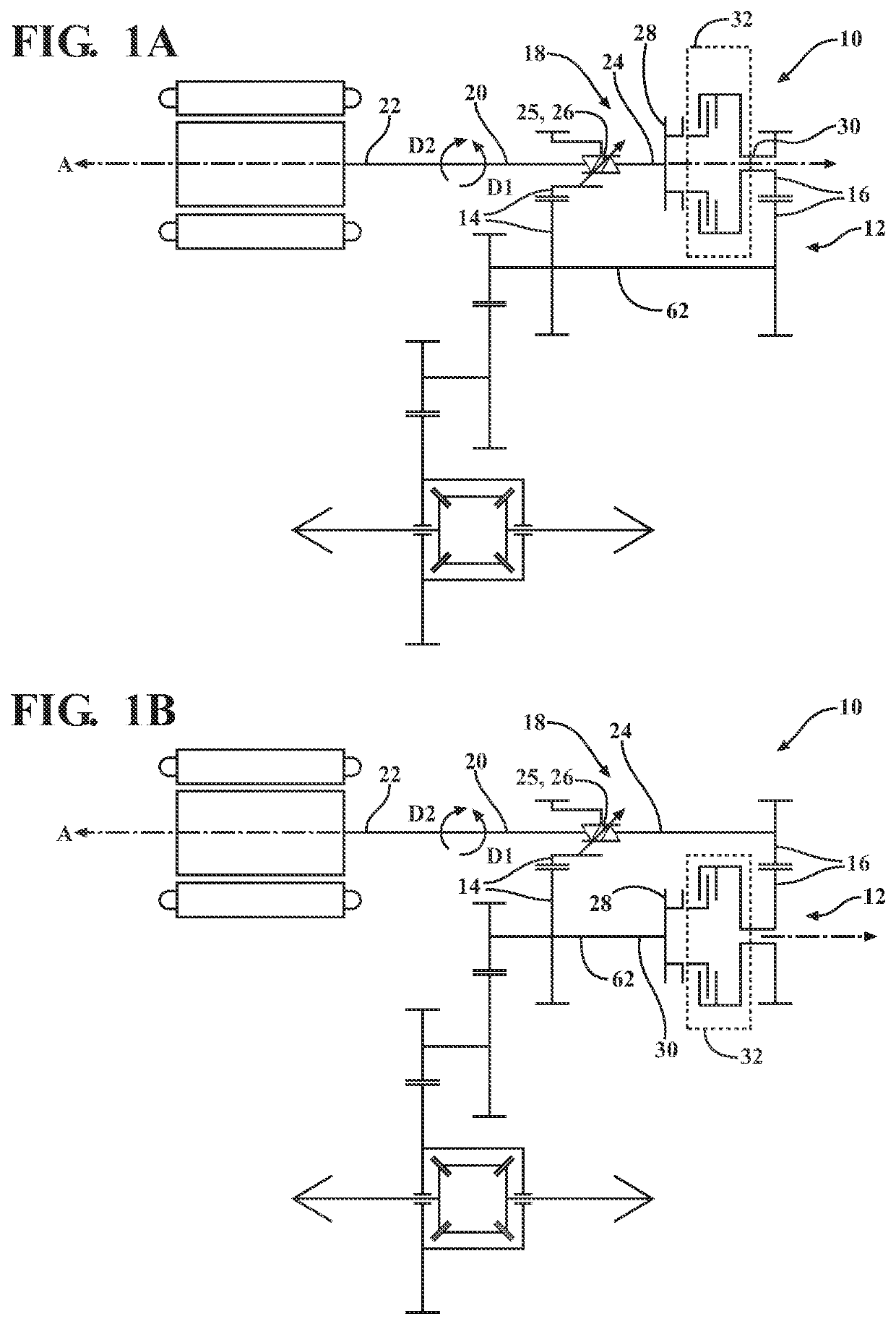
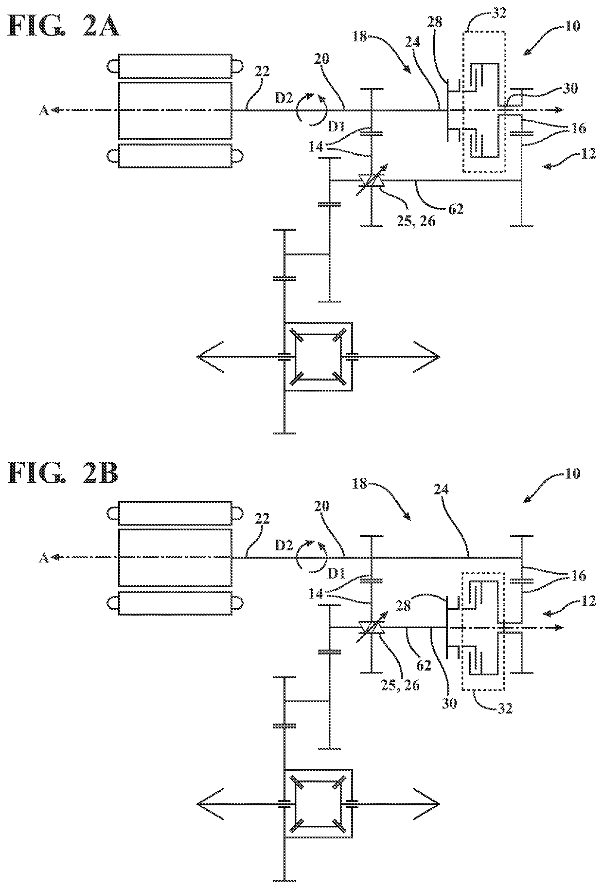
[0035]With reference to the Figures, wherein like numerals indicate like parts throughout the several views, a vehicle transmission 10 is provided in schematic illustration in FIGS. 1A-2B. The vehicle transmission 10 has a gearset 12 including a first gear ratio 14 and a second gear ratio 16 different from the first gear ratio 14. A shifting system 18 for the vehicle transmission 10 is shown in FIGS. 1A-2B.

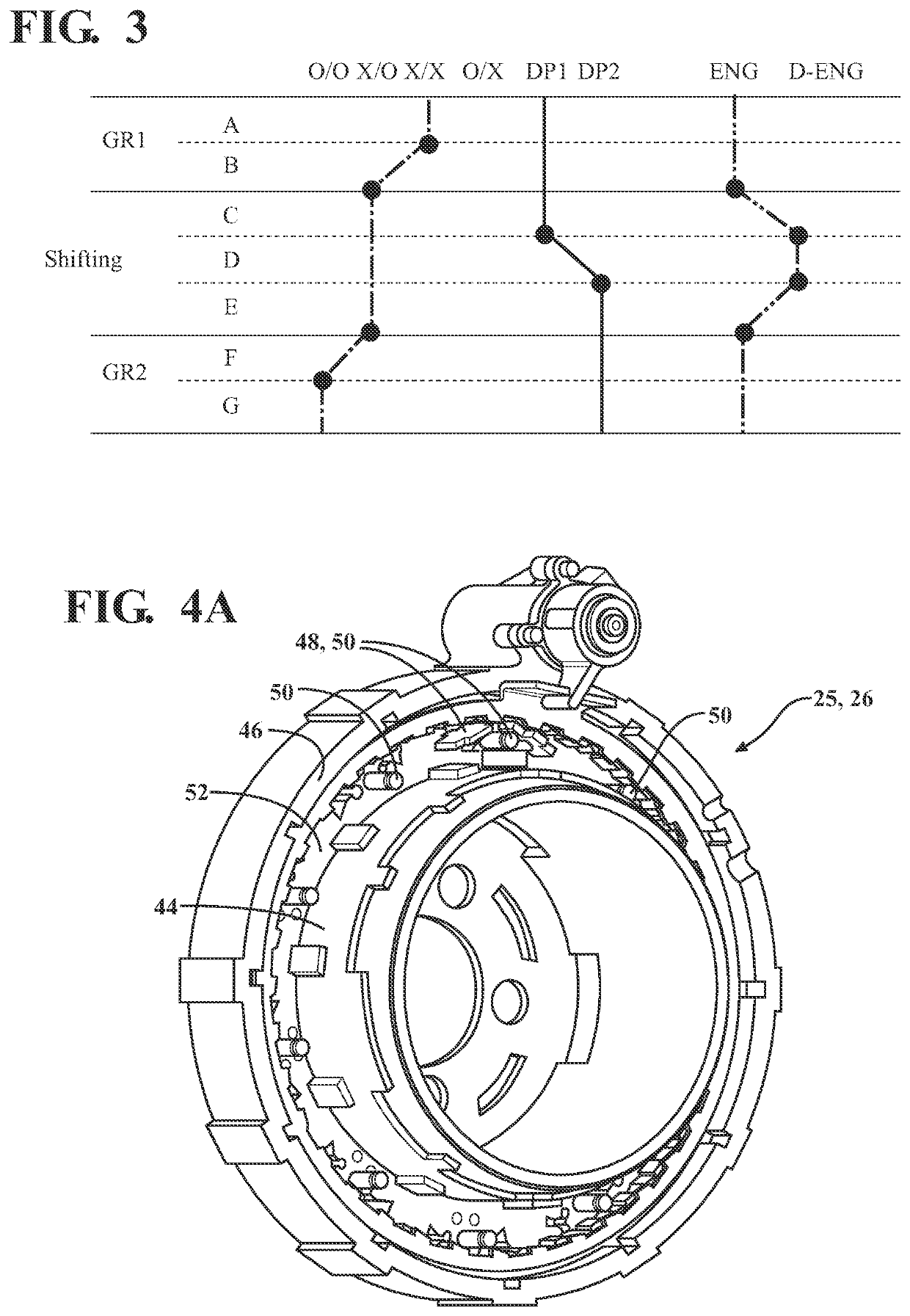
[0036]The shifting system 18 includes an input member 20 extending along an axis A between a first end 22 and a second end 24 spaced from the first end 22. The input member 20 is rotatable about the axis A. As non-limiting examples, the input member 20 may be a shaft or a gear. The shifting system 18 also includes a selectable one-way clutch 26 rotatably coupled to the input member 20, and the selectable one-way clutch 26 is moveable between a first clutch position (denoted as X / X in FIG. 3), a second clutch position (denoted as X / O in FIG. 3), and a third clutch position (denoted...


PUM


Abstract

A shifting system for a vehicle transmission includes an input member and a selectable one-way clutch rotatably coupled to the input member. The selectable one-way clutch is moveable between first, second, and third clutch positions. The shifting system also includes a disconnect coupled to the input member and moveable between first and second disconnect positions, and an output member selectively rotatable with the input member. The shifting system further includes a shifting assembly for selectively rotatably coupling the input and output members. The shifting assembly includes an input hub coupled to the input member, having a disconnectable component engageable with the disconnect, and having a clutch engagement component. Clutch plates are coupled to the clutch engagement component and are moveable between engaged and disengaged positions. A clutch plate carrier is coupled to the clutch plates and output member to transmit torque from the clutch engagement component to the output member.

Description

CROSS-REFERENCE TO RELATED APPLICATIONS[0001]The present application claims priority to and all the benefits of U.S. Provisional Patent Application No. 62 / 946,156 filed on Dec. 10, 2019, and 63 / 091,775 filed on Oct. 14, 2020, which are expressly incorporated herein by reference in their entirety.BACKGROUND OF THE INVENTION1. Field of the Invention[0002]The present invention generally relates to a shifting system for a vehicle transmission, and to a method of operating the shifting system.2. Description of the Related Art[0003]Conventional vehicles known in the art typically include a motor having a rotational output as a rotational input into a vehicle transmission. The motor is typically an internal combustion engine or an electric motor, and generates the rotational output which is selectively transferred to the vehicle transmission which, in turn, transfers rotational torque to one or more wheels of the vehicle. The vehicle transmission changes the rotational speed and torque gen...

Claims


Application Information

Patent Timeline
Patent Type & Authority Patents(United States)
IPC IPC(8): F16D41/16F16D41/12F16D28/00F16H3/66F16H63/30
CPCF16D41/125F16D28/00F16D41/16F16H3/66F16H2063/3093F16H3/091F16H3/10F16H59/02F16H61/04F16H57/023F16D23/02F16D23/025F16H2003/0818F16H2003/0811F16H2057/02034F16H2057/02043F16H2200/0021F16H2200/0034B60Y2200/91F16H3/089F16D41/08F16D41/082
Inventor CAMPTON, CALAHAN B.MARTIN, R. KEITH
Owner BORGWARNER INC
Learn More