
Switch assisted diode-clamped energy harvesting system for variable capacitance transducers

a diode-clamped, variable capacitance technology, applied in the direction of measuring devices, electrostatic generators/motors, instruments, etc., can solve the problems of relatively low energy capture ability of the energy harvesting system of the prior art and low efficiency at particularly small capacitance variation levels, so as to improve the effect of the charging and discharging cycl

Active Publication Date: 2022-01-04
SINGLE BUOY MOORINGS INC
View PDF7 Cites 1 Cited by
  • Summary
  • Abstract
  • Description
  • Claims
  • Application Information

AI Technical Summary

Benefits of technology

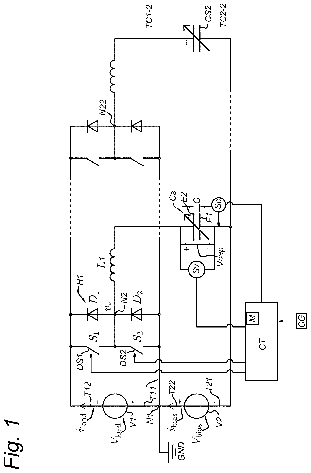
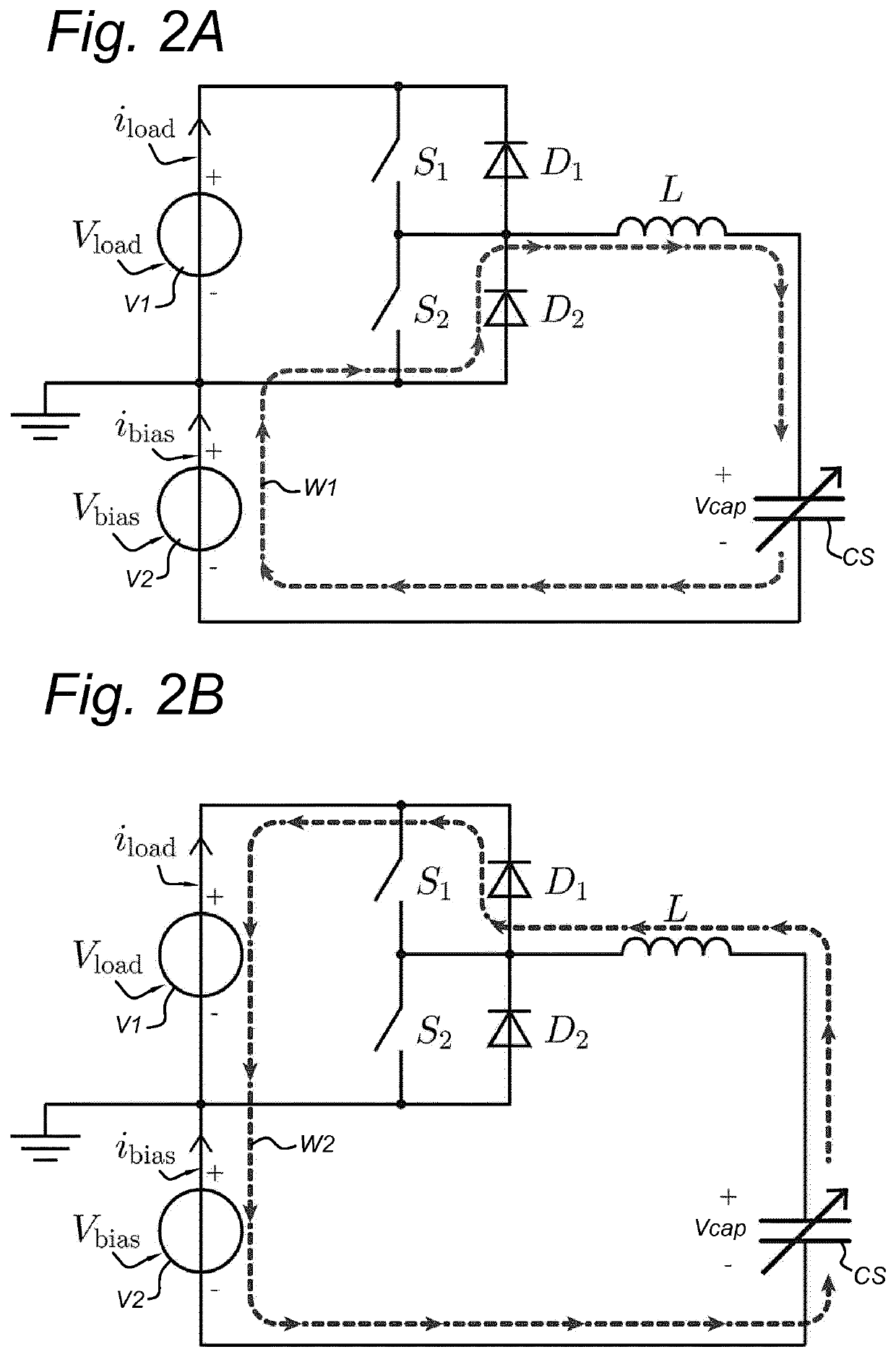
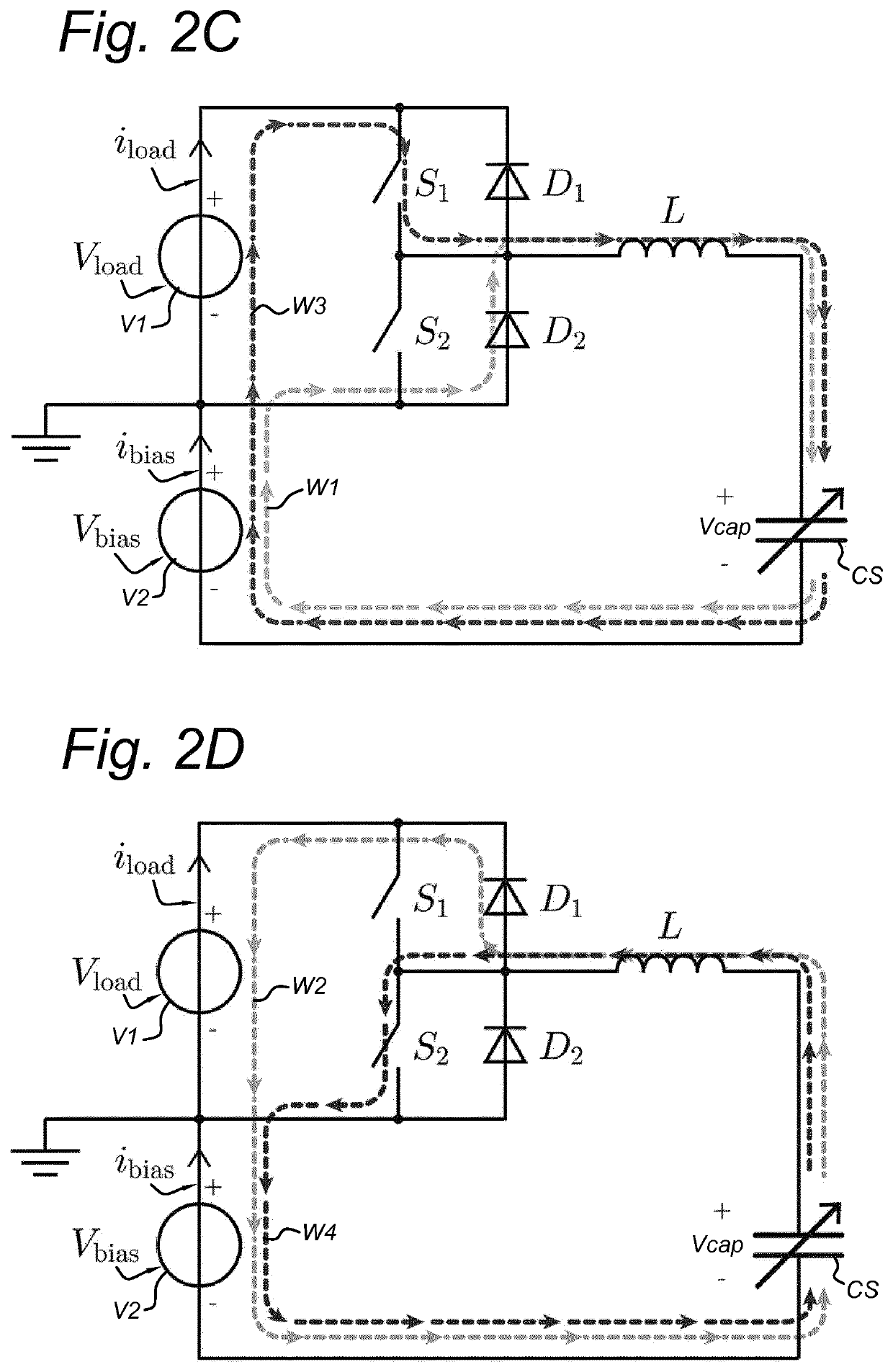
[0006]By incorporating for each variable capacitor an inductor, a first switch and a second switch in which the inductor is connected between the common node and the first capacitor terminal of the respective variable capacitor, and in which the first switch is connected in parallel with the first diode and the second switch is connected in parallel with the second diode, an additional step-up and step-down converter is implemented. In addition, in the energy harvesting system according to the invention, the second voltage source provides a bias source to the source side such that the active components are exposed to lower voltages for the same variable capacitor voltage. As a result, less energy conversion is required which results in relatively lower losses, in comparison with the energy harvesting system of the prior art.
[0011]According to the method of the invention, the charging of the variable capacitor is extended upto a comparatively larger charge than possible by passively charging of the variable capacitor. Also, the discharging of the variable capacitor is extended to a comparatively smaller resulting charge than in the prior art. As a result, the effectiveness of the charging and discharging cycle is improved.

Problems solved by technology

The energy harvesting system of the prior art has a relatively low energy capture ability, especially for small capacitance variation levels.
As a result it has a low efficiency at particularly small capacitance variation levels due to dielectric losses which are roughly constant and independent of the capacitance variation.

Method used


Image

  • Switch assisted diode-clamped energy harvesting system for variable capacitance transducers
  • Switch assisted diode-clamped energy harvesting system for variable capacitance transducers
  • Switch assisted diode-clamped energy harvesting system for variable capacitance transducers

Examples


Embodiment Construction

[0020]FIG. 1 shows schematically a circuitry of an energy harvesting system according to an embodiment of the invention.

[0021]An energy harvesting system 100 according to an embodiment of the invention is configured for harvesting energy from one or more variable capacitors Cs. Such variable capacitors Cs can be based on electro-active polymer devices. Electro-active polymer devices function as electrostatic energy transducers that convert mechanical energy into electrical energy. Such transducers consist of at least one pair of electrodes that are positioned opposite each other and are separated by a gap that comprises a deformable dielectric, constituting a variable capacitor whose capacitance varies with the level of imposed deformation.

[0022]Operating such an electrostatic energy transducer to harvest mechanical energy is achieved by cyclically applying electric charges on the capacitor structure at a state of maximum deformation and subsequently removing the charges at a state ...


PUM

PropertyMeasurementUnit
frequencyaaaaaaaaaa
distanceaaaaaaaaaa
electrical energyaaaaaaaaaa

Abstract

An electrical energy harvesting system includes at least one variable capacitor, preferably of electro-active polymer, two voltage sources, and a half-bridge network. The voltage sources are arranged in series with an interconnecting node between a first polarity terminal of the first voltage source and a second opposite polarity terminal of the second voltage source. For each variable capacitor the half-bridge network includes a pair of diodes in series with a common node therebetween, connected in parallel with the first voltage source, an inductor connected between the common node and a first terminal of the variable capacitor, a first switch in parallel with the first diode, and a second switch in parallel with the second diode. The second terminal of the variable capacitor is connected to the first polarity terminal of the second voltage source.

Description

FIELD OF THE INVENTION[0001]The present invention relates to an energy harvesting system for harvesting electrical energy from at least one variable capacitor. Moreover, the invention relates to a method for harvesting electrical energy from at least one variable capacitor using such an energy harvesting system.PRIOR ART[0002]WO 2010 / 146457 discloses an environmental electrical generator having variable capacitors that each includes a repeatedly stretched and relaxed sheet of stretchable material and electrodes lying against opposite faces of the sheet, which includes a power extraction unit coupled to the electrodes of at least a pair of capacitors. The unit directs an electrical charge (current) from a first pair of electrodes that have a higher voltage, to one or more second pairs of electrodes that have a lower voltage, to recharge the second pairs of electrodes. During the current flow, electrical power is extracted by the drop-in voltage of current passing through the unit. Th...

Claims


Application Information

Patent Timeline
Patent Type & Authority Patents(United States)
IPC IPC(8): H02N1/00G01R19/00
CPCH02N1/00G01R19/0046H02N2/181
Inventor VAN KESSEL, RICK
Owner SINGLE BUOY MOORINGS INC
Learn More