Circuit arrangement for the control of at least one electric machine

a technology for electric machines and circuits, applied in the direction of electric propulsion mounting, battery/fuel cell control arrangement, electric propulsion, etc., can solve the problems of no indication, excess electrical energy consumption,

Inactive Publication Date: 2008-03-04
ZF FRIEDRICHSHAFEN AG
View PDF9 Cites 1 Cited by
  • Summary
  • Abstract
  • Description
  • Claims
  • Application Information

AI Technical Summary

Benefits of technology

[0011]In a particularly advantageous way, the above measure makes it possible to make available a higher power of the electric machine in a very short time when necessary. Likewise, the life of the storage device I or accumulator is extended considerably, since substantially less energy conversion takes place in it.
[0013]As the invention further provides, the switching device can be arranged inside a housing of the DC / AC converter, this enabling the structure to be simplified and also the coolants, supply voltages, etc., associated with the circuit of the DC / AC converter to be used for the switching device as well. Besides, all other signals required for the control of the electric machine are available in the DC / AC converter.
[0016]For operating situations in which a lot of energy has to be converted in a short time, the switching device is designed such that energy conversion can be transferred from storage device I to storage device II.

Problems solved by technology

In addition, the motor vehicle's electrical system comprises at least one electricity consumer which, for its part, can be connected to the electrical drive device when the specified charge condition of the electrical energy storage device has been reached, particularly during generator operation, so that it consumes excess electrical energy.
The known technical solutions do not give any indication of how operating conditions, for example of a vehicle, can be managed appropriately when the conditions demand high drive-power peaks of short duration.

Method used


Image

  • Circuit arrangement for the control of at least one electric machine
  • Circuit arrangement for the control of at least one electric machine
  • Circuit arrangement for the control of at least one electric machine

Examples


Embodiment Construction

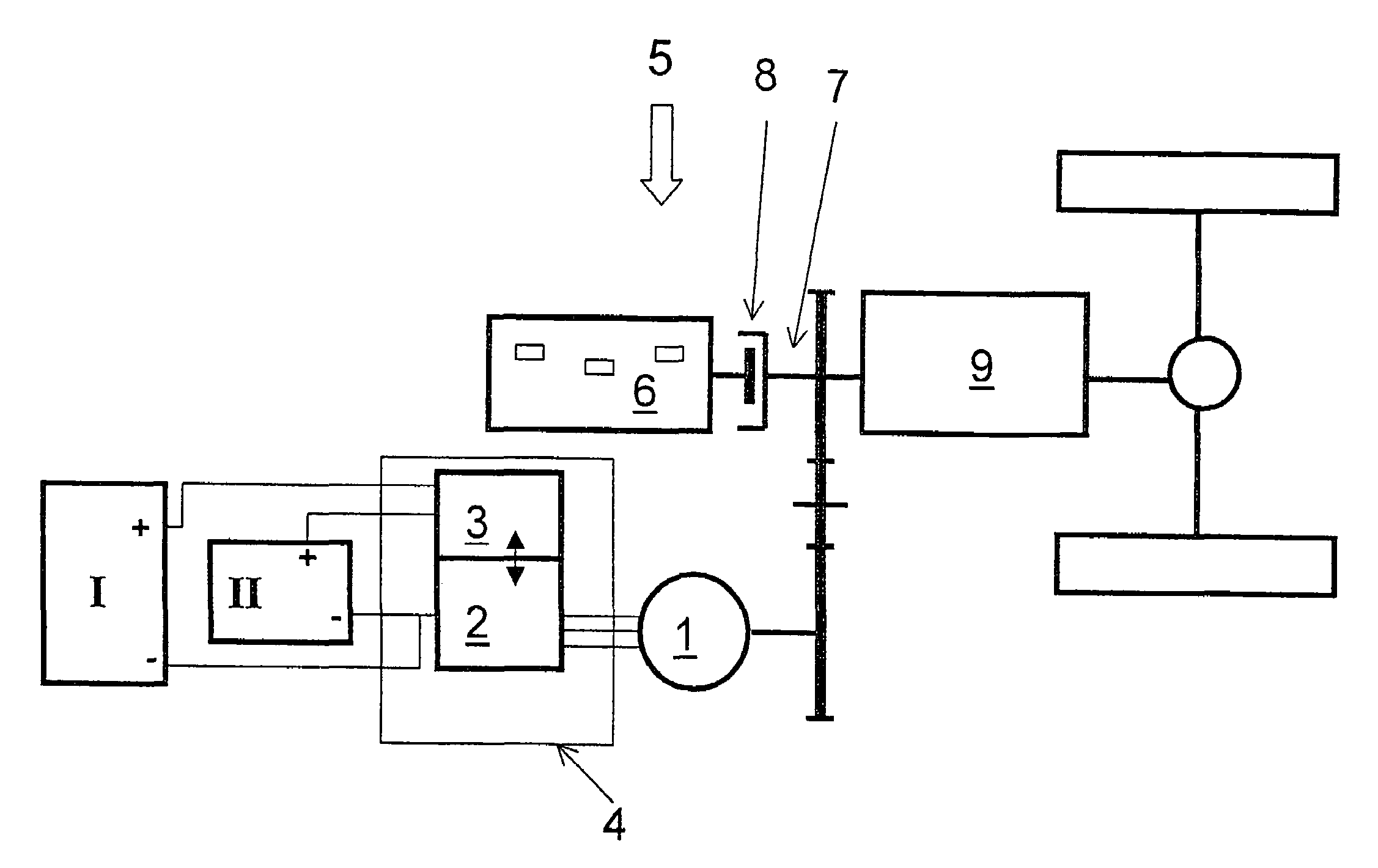
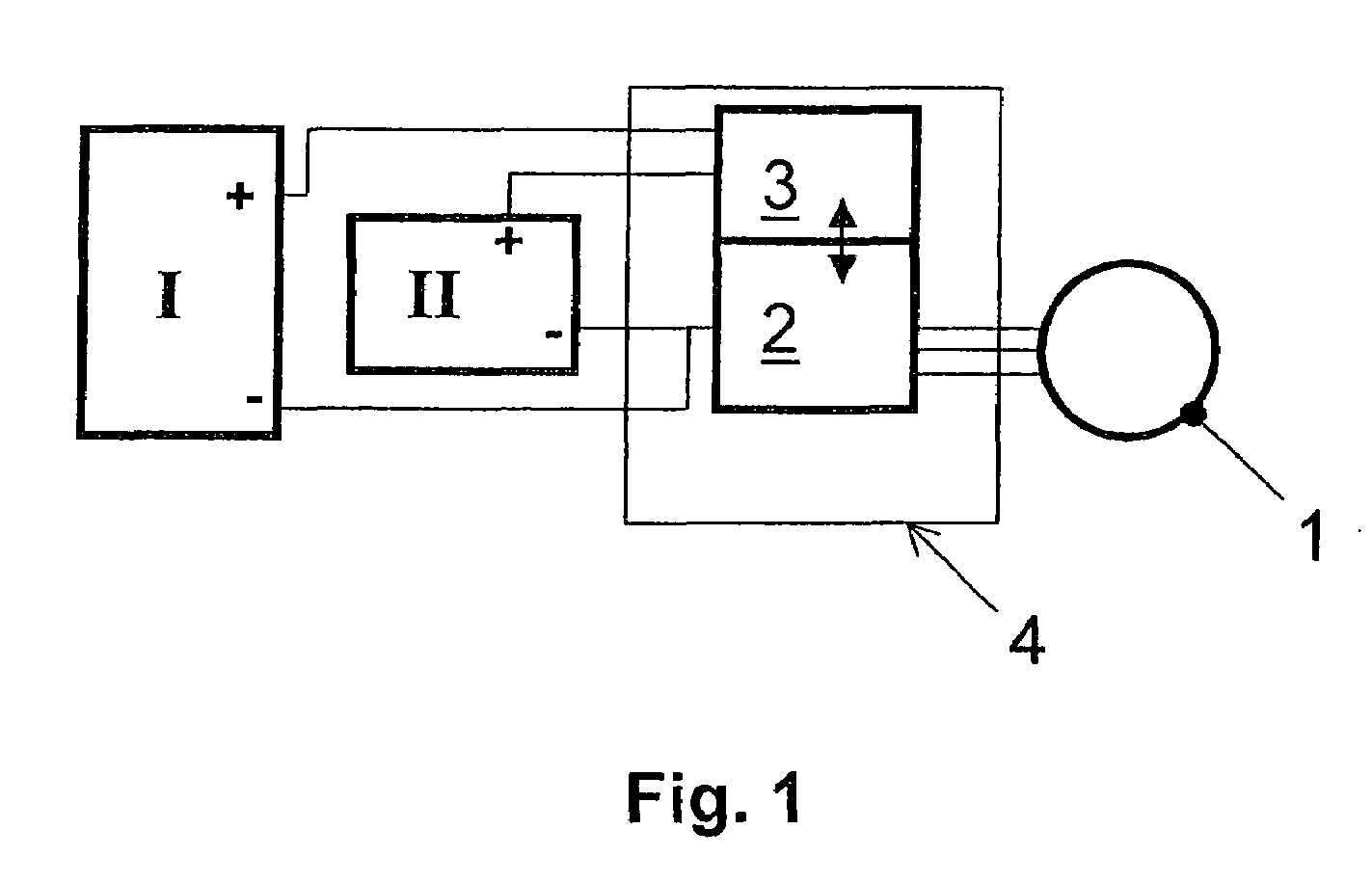
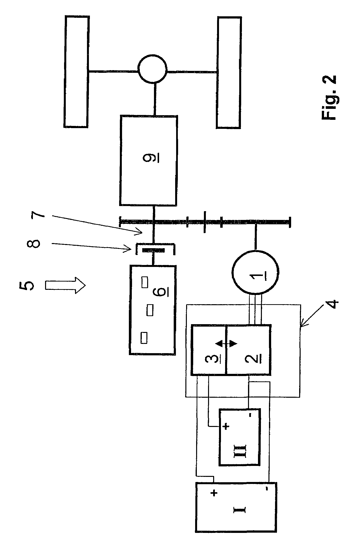
[0024]Thus, FIG. 1 illustrates first the circuit arrangement for the control of at least one electric machine 1, shown on its own, preferably in the form of an asynchronous or synchronous machine, such that the electric machine 1 can be connected to an energy supply in a manner known as such via a conventional DC / AC converter 2, whose features and mode of action have long been familiar to those with knowledge of the field, and in addition via at least one switching device 3.

[0025]According to the invention the energy supply consists of two different electrical energy storage devices I, II, one device I being designed as a storage device for long-lasting power demands and the other device II as a storage device for short and high power-peak demands.

[0026]By way of the switching device 3 it is ensured that when the electric machine 1 is operated as an electric motor, short and high power-peak demands are covered from the storage device II, while the storage device I contributes mainly...


PUM


Abstract

The objective of providing a circuit arrangement for the control of at least one electric machine (1), which is suitable for also enabling operating conditions of the electric machine (1) that demand high power-peaks of short duration, is essentially achieved in that the electric machine (1) can be connected via a DC / AC converter (2) and at least one switching device (3) to at least two different electrical energy storage devices (I, II), one storage device (I) being designed as a storage device for comparatively long-lasting power demands and the other storage device (II) as a storage device for short and high power-peaks.

Description

[0001]This application claims priority from German Application Serial No. 10 2004 053 074.2 filed Nov. 3, 2004.FIELD OF THE INVENTION[0002]The invention concerns a circuit arrangement for the control of at least one electric machine.BACKGROUND OF THE INVENTION[0003]DE 199 35 873 A1 discloses a circuit arrangement for a hybrid vehicle which has a traction battery, an electric motor and an internal combustion engine which works independently thereof. The circuit arrangement, which serves on the one hand to drive the electric motor by means of the accumulator and on the other hand to charge the latter, comprises a direct voltage intermediate circuit and a first DC / AC converter which, for its part, is connected to the electric motor. In addition, a second DC / AC converter is present in the circuit arrangement, which is connected, on the one hand, to the direct voltage intermediate circuit and, on the other hand, to a generator associated with the combustion engine for charging the accumu...

Claims


Application Information

Patent Timeline
Patent Type & Authority Patents(United States)
IPC IPC(8): B60K1/00
CPCB60L11/1868B60L15/209B60L11/1803B60L2210/40Y02T10/7275Y02T10/7066Y02T10/7241Y02T10/7005B60L50/51B60L58/20Y02T10/70Y02T10/64Y02T10/72
Inventor GRIESMEIER, UWEKETT, JURGEN
Owner ZF FRIEDRICHSHAFEN AG
Why Eureka
Try Eureka