
Rotor blade with serrations

a technology of rotor blades and serrations, which is applied in the field of rotor blades, can solve the problems of affecting the noise generated by the wind turbine, causing the noise generation of the trailing edge section of the rotor blade, and being a major source of nois

Active Publication Date: 2022-01-11
SIEMENS GAMESA RENEWABLE ENERGY AS
View PDF32 Cites 2 Cited by
  • Summary
  • Abstract
  • Description
  • Claims
  • Application Information

AI Technical Summary

Benefits of technology

[0009]An aspect relates to a rotor blade for a wind turbine with an improved noise reduction potential.
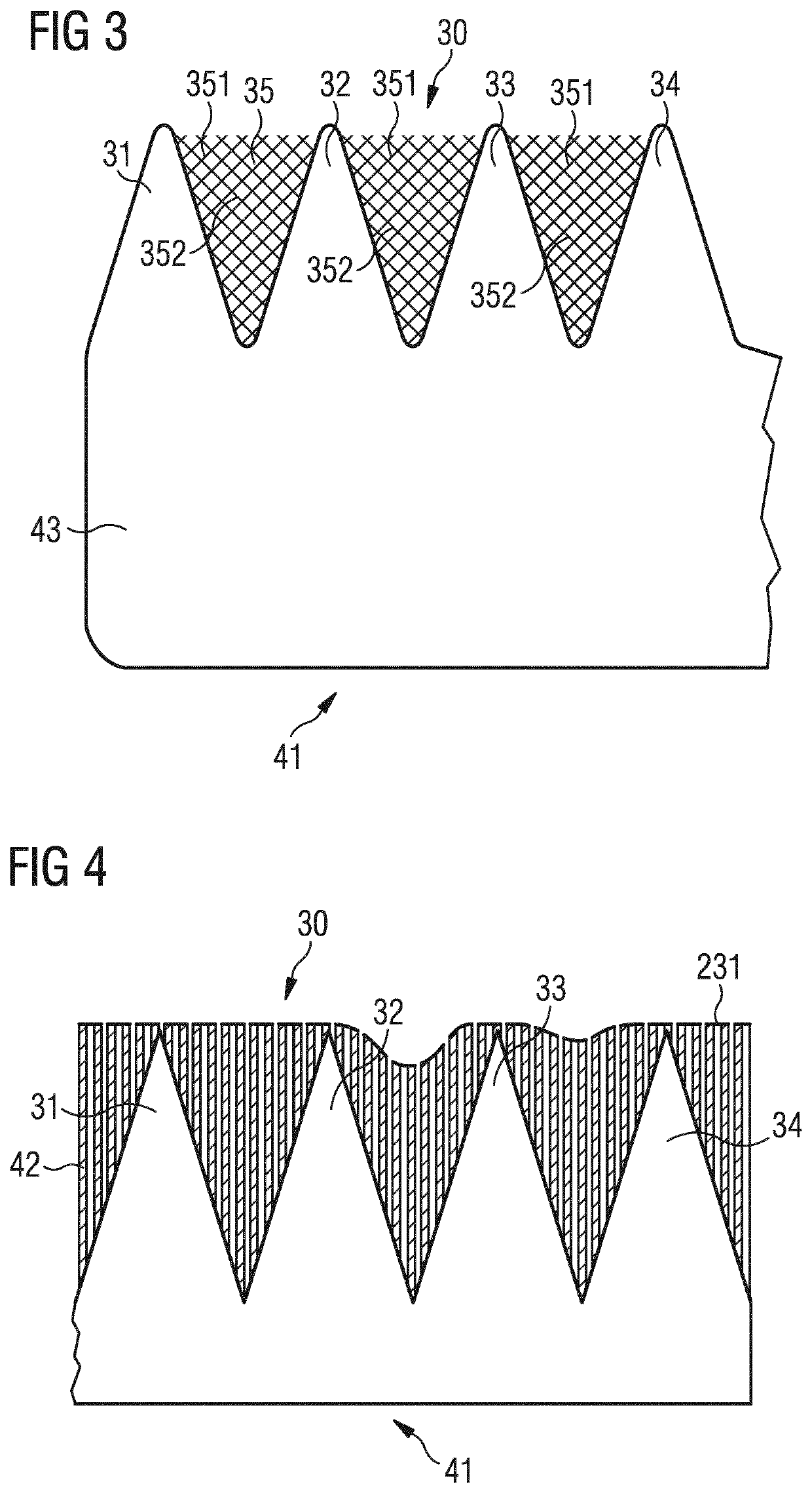
[0010]According to one aspect of embodiments of the invention, there is provided a rotor blade for a wind turbine, wherein the rotor blade comprises serrations along at least a portion of the trailing edge section of the rotor blade. The serrations comprise a first tooth and at least a second tooth, wherein the first tooth is spaced apart from the second tooth. Furthermore, the area between the first tooth and the second tooth is at least partially filled with porous material such that generation of noise in the trailing edge section of the rotor blade is reduced.
[0011]A key aspect of embodiments of the present invention is that by providing porous material in between two adjacent teeth of the serrations, noise which is generated by the merging airflow from the pressure side and the suction side between the adjacent teeth is reduced. In other words, while in a rotor blade with conventional serrations, the jet of airflow which passes through the teeth, i.e. which passes through the gap or interstice between two adjacent teeth, generate noise due to the pressure recovery from the pressure side and the suction side of the rotor blade, the porous material between the adjacent teeth allows the pressure gradient in the flow direction across the trailing edge to equalize more slowly. Consequently, a reduction in the magnitude of the acoustic emission may be achieved.

Problems solved by technology

During rotation of a rotor blade about the rotational axis of the rotor of a wind turbine, noise is generally generated at the trailing edge section of the rotor blade.
Among other things, the major source of noise is the interaction of turbulent structures in the boundary layer with the trailing edge.
Additionally, mixing of the flow from suction and pressure side of the rotor blade past the trailing edge, which is also referred to as flow recovery, can lead to turbulence which can also adversely impact the noise generated from the wind turbine.
This noise may be an issue, especially if the wind turbine is installed onshore near a residential area.
However, the noise reduction which can be achieved by applying one of the mentioned concepts may be insufficient and unsatisfying.
In addition, they may be further bent or deviated out of the chordal plane under certain, in particular heavy, loading of the trailing edge section of the rotor blade.

Method used


Image

  • Rotor blade with serrations
  • Rotor blade with serrations
  • Rotor blade with serrations

Examples


Embodiment Construction

[0077]The illustration in the drawings is in schematic form. It is noted that in different figures, similar or identical elements may be provided with the same reference signs.

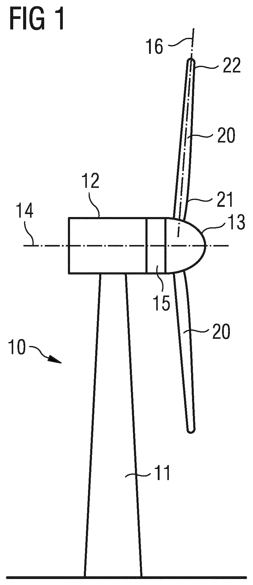
[0078]In FIG. 1, a wind turbine 10 is shown. The wind turbine 10 comprises a nacelle 12 and a tower 11. The nacelle 12 is mounted at the top of the tower 11. The nacelle 12 is mounted rotatable with regard to the tower 11 by means of a yaw bearing. The axis of rotation of the nacelle 12 with regard to the tower 11 is referred to as the yaw axis.

[0079]The wind turbine 10 also comprises a hub 13 with three rotor blades 20 (of which two rotor blades 20 are depicted in FIG. 1).

[0080]The hub 13 is mounted rotatable with regard to the nacelle 12 by a main bearing. The hub 13 is mounted rotatable about a rotor axis of rotation 14.

[0081]The wind turbine 10 furthermore comprises a main shaft, which connects the hub 13 to a rotor of a generator 15. The hub 13 is connected directly to the rotor of the generator 15, thus ...


PUM

PropertyMeasurementUnit
angleaaaaaaaaaa
porosityaaaaaaaaaa
porosityaaaaaaaaaa

Abstract

A method using machine learned, scenario based control heuristics including: providing a simulation model for predicting a system state vector of the dynamical system in time based on a current scenario parameter vector and a control vector; using a Model Predictive Control, MPC, algorithm to provide the control vector during a simulation of the dynamical system using the simulation model for different scenario parameter vectors and initial system state vectors; calculating a scenario parameter vector and initial system state vector a resulting optimal control value by the MPC algorithm; generating machine learned control heuristics approximating the relationship between the corresponding scenario parameter vector and the initial system state vector for the resulting optimal control value using a machine learning algorithm; and using the generated machine learned control heuristics to control the complex dynamical system modelled by the simulation model.

Description

CROSS-REFERENCE TO RELATED APPLICATIONS[0001]This application claims priority to PCT Application No. PCT / EP2016 / 058428, having a filing date of Apr. 15, 2016, based off of European Application No. 15168714.2 having a filing date of May 21, 2015, the entire contents of which are hereby incorporated by reference.FIELD OF TECHNOLOGY[0002]The following relates to a rotor blade for a wind turbine which is configured such that generation of noise in the trailing edge section of the rotor blade is reduced compared to conventional rotor blades. The following furthermore relates to a wind turbine comprising at least one of such a rotor blade.BACKGROUND[0003]During rotation of a rotor blade about the rotational axis of the rotor of a wind turbine, noise is generally generated at the trailing edge section of the rotor blade. Among other things, the major source of noise is the interaction of turbulent structures in the boundary layer with the trailing edge. Literature shows that most noise is ...

Claims


Application Information

Patent Timeline
Patent Type & Authority Patents(United States)
IPC IPC(8): F03D1/06B32B3/30B32B5/18
CPCF03D1/0675B32B3/30B32B5/18F03D1/0633B32B2603/00F05B2240/122F05B2240/311F05B2240/32F05B2250/11F05B2250/181F05B2250/183F05B2250/184F05B2250/292F05B2250/611F05B2260/96F05B2280/6002F05B2280/6012F05B2280/6013Y02E10/72F05B2240/3042
Inventor ASHEIM, MICHAEL J.SINGH, MANJINDER J.
Owner SIEMENS GAMESA RENEWABLE ENERGY AS
Learn More