
Dimming track lamp

a track lamp and dipole technology, applied in the field of dipole lamps, can solve the problems of increased production costs, unfavorable user personalized changes, complex overall structure of lamps, etc., and achieve the effects of small track volume, high power, and small track

Active Publication Date: 2022-01-11
SELF ELECTRONICS CO LTD +2
View PDF4 Cites 2 Cited by
  • Summary
  • Abstract
  • Description
  • Claims
  • Application Information

AI Technical Summary

Benefits of technology

The present invention is a dimming track lamp that has a compact design and can be used in small tracks. It allows for independent adjustment of brightness and color temperature while also integrating a control circuit board that can quickly export heat. The assembly housing of the lamp includes a rotation limiting member to prevent excessive rotation of the rotary connecting rod, which ensures stable operation. The design of the lamp also facilitates manufacturing a smaller volume and higher power.

Problems solved by technology

But most of the existing LED spotlights still need wire when install them, that is, the wire can't be separated from the LED spotlight during the assembly, the existence of the wire leads to the need to provide additional space for laying the wire, resulting in increased production costs, more importantly, this makes the overall structure of the lamp complex, when there is a problem, the maintenance is not convenient, and the wire is easy to cause safety problems such as aging.
At the same time, this kind of the lamp combination design is not conducive to the user's personalized change according to the demand.

Method used


Image

  • Dimming track lamp
  • Dimming track lamp
  • Dimming track lamp

Examples


Embodiment Construction

[0029]The present application is illustrated by way of the following detailed description based on of the accompanying drawings. It should be noted that illustration to the embodiment in this application is not intended to limit the invention.

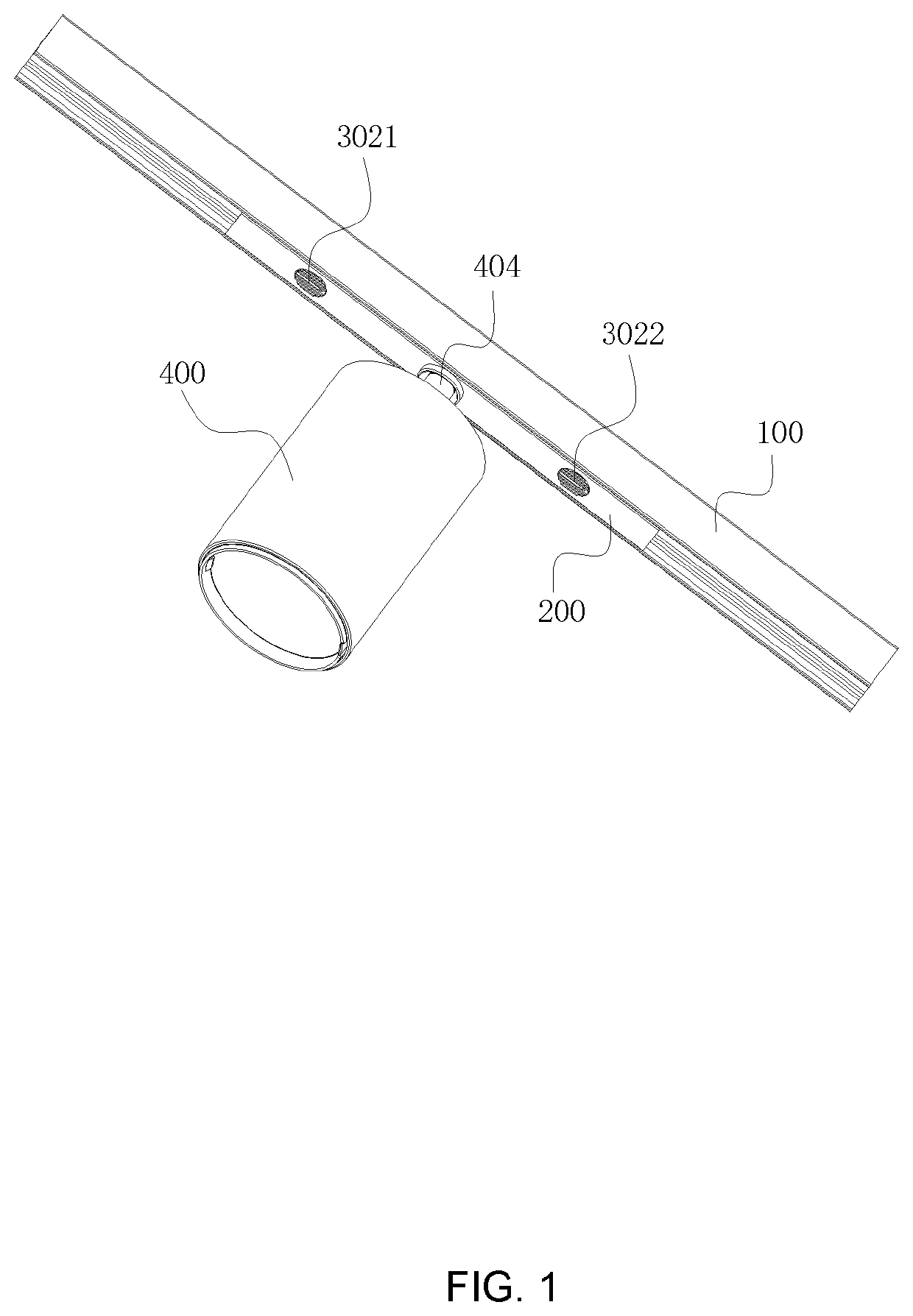
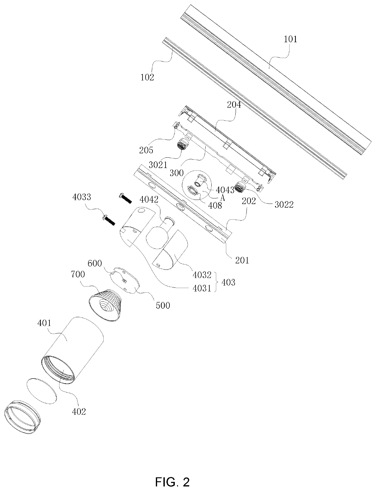
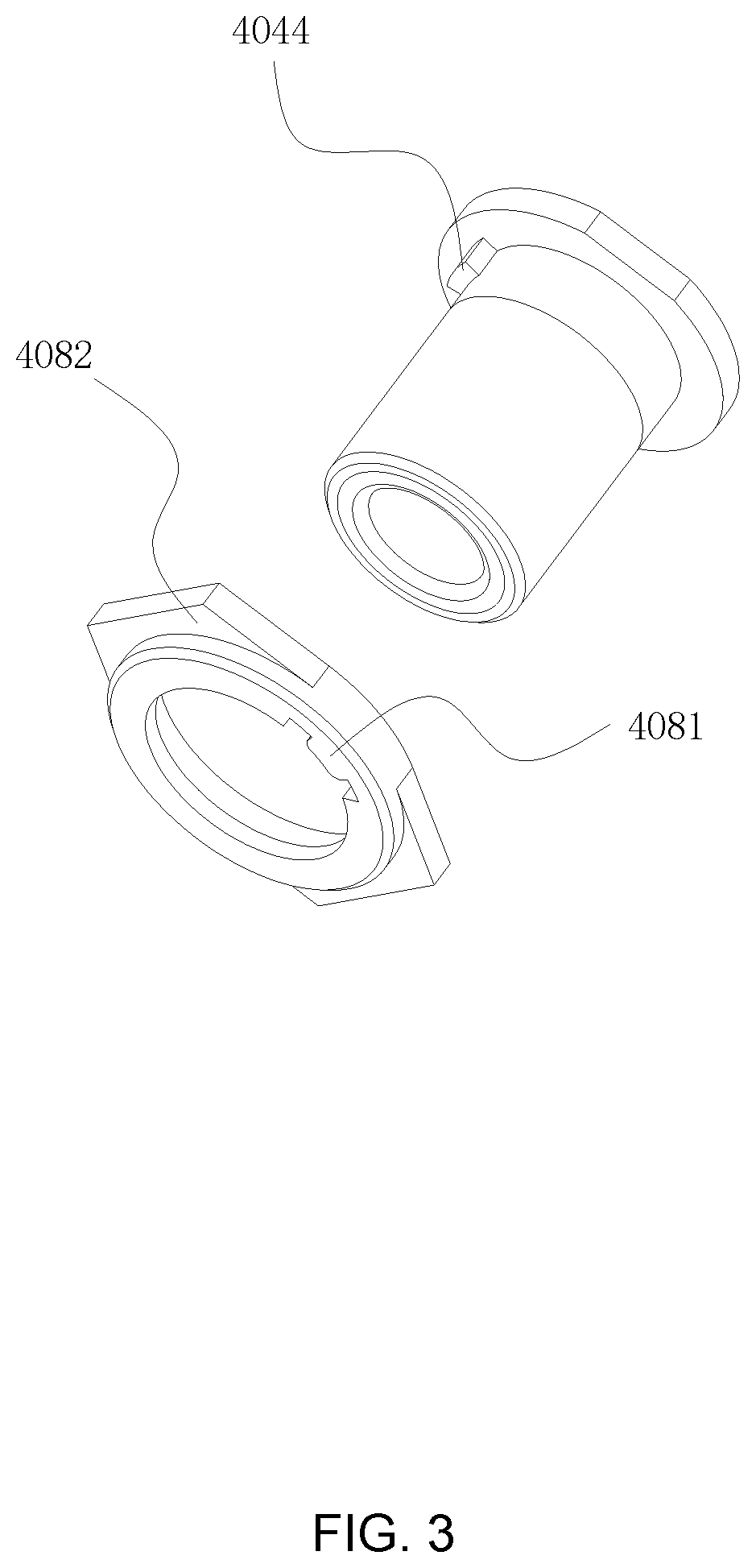
[0030]Referring to FIG. 1 to FIG. 8, a dimming track lamp in this embodiment comprises an assembly housing 200 which is in detachable connection with the power supply track 100, a control circuit board 300 is in the assembly housing 200 and electrically connected with the power supply track 100, a lamp body 400 arranged on the assembly housing 200, a printed circuit board 500 arranged in the lamp body 400, a light source 600 on the printed circuit board 500 and an optical element 700 arranged in the light output direction of the light source 600, the control circuit board 300 comprises: a power supply module 301 which is electrically connected with the power supply track 100, a signal input module 302, a signal processing module 303 for analyzi...


PUM


Abstract

A dimming track lamp has a detachable assembly housing with a power supply track, a control circuit board electrically connected with the power supply track, a lamp body arranged on the assembly housing, a printed circuit board arranged in the lamp body, a light source on the printed circuit board and an optical element arranged in the light output direction of the light source. The control circuit board has a power supply module which is electrically connected with the power supply track, a signal input module, a signal processing module for analyzing and calculating the input signal and generating a control signal, and a signal output module for outputting the control signal to the printed circuit board. The light source has a warm light source and a cold light source, the control signal is used to control the light output of the warm light source and the cold light source.

Description

[0001]This application claims priority to a Chinese Patent Application No. CN 202010119573.1, filed on Feb. 26, 2020.FIELD OF THE TECHNOLOGY[0002]The present invention relates to the technical field of lighting equipment, with particular emphasis on a dimming track lamp.BACKGROUND[0003]LED is widely used in daily life because of it has the characteristics of high luminous efficiency, energy efficiency and so on. At present, LED spotlights are often used in cabinets, markets and showrooms to provide lighting.[0004]But most of the existing LED spotlights still need wire when install them, that is, the wire can't be separated from the LED spotlight during the assembly, the existence of the wire leads to the need to provide additional space for laying the wire, resulting in increased production costs, more importantly, this makes the overall structure of the lamp complex, when there is a problem, the maintenance is not convenient, and the wire is easy to cause safety problems such as ag...

Claims


Application Information

Patent Timeline
Patent Type & Authority Patents(United States)
IPC IPC(8): F21V21/35H05B45/20H05B45/10F21V21/29F21V23/00F21V23/02H05B39/02H05B39/06F21Y113/13F21Y115/10F21V17/02F21V19/02F21V21/14
CPCF21V21/35F21V21/29F21V23/005F21V23/02H05B39/02H05B39/06H05B45/10H05B45/20F21Y2113/13F21Y2115/10F21S8/00F21V23/04F21V15/01F21V21/14F21S8/038F21V23/006F21V23/0435
Inventor FANG, LEIYU, JIANFENGHE, ZUPINGDONG, JIANGUOXU, KAIYANG, JUN
Owner SELF ELECTRONICS CO LTD
Learn More