Modular pit structure for a lifting system, such lifting system and method for building such pit structure

a technology of modular pit structure and lifting system, which is applied in the direction of lifting frames, lifting devices, industrial buildings, etc., can solve the problems of time-consuming and labor-intensive and the installation of conventional pit structure requires substantial manufacturing, transportation and handling costs, so as to improve the stability and accuracy of the assembled pit structure, the effect of effective installation

Active Publication Date: 2022-01-18
STERTIL
View PDF24 Cites 0 Cited by
  • Summary
  • Abstract
  • Description
  • Claims
  • Application Information

AI Technical Summary

Benefits of technology

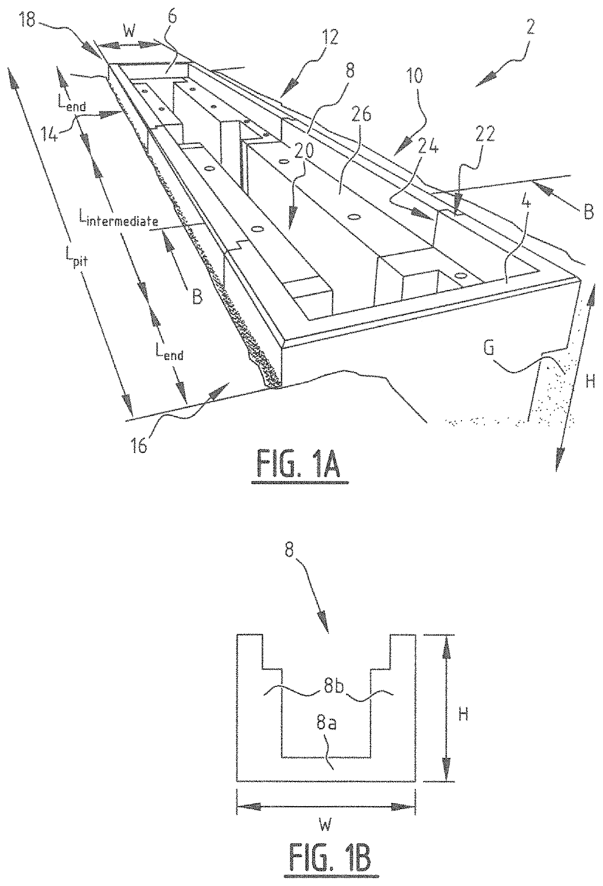
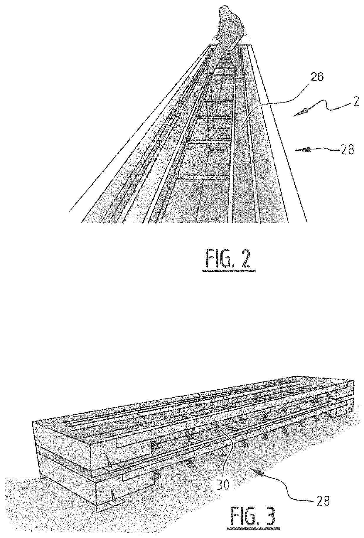
[0014]The intermediate parts of the modular pit structure have a length, a width and a height. Preferably, the length and width are predefined. In an installed state of the pit structure, after assembly of the components of the modular pit structure, the length of the intermediate part extends in a substantially horizontal direction between the first and second end parts and the height of the intermediate part extends in a substantially vertical direction. This provides modular parts that can be manufactured, transported and handled relatively easily. This renders manufacturing of a pit structure less time consuming. Furthermore, the use of modular parts enables installing a pit structure accurately.
[0017]In a further embodiment of the invention, the intermediate parts have a U-shape. These U-shape modular intermediate parts provide an effective modular part for the modular pit structure. Such U-shaped intermediate parts can be installed effectively and provide an accurate pit structure that can be installed in accordance with the desired specifications. As a further advantage the U-shaped modular parts provide two side walls (segments) and a pit floor (segment) in a single modular part.
[0018]In a preferred embodiment of the invention the connection between adjacent parts of the pit structure comprises a so-called form closure to which is also referred to as an embodiment of an interlock. This interlock is preferably constructed as a tongue and groove connection with a suitable sealant to make a substantially watertight connection between the parts. This closure or interlock further improves the stability and accuracy of the assembled pit structure with the modular elements according to the invention.

Problems solved by technology

Conventional pit structures require substantial manufacturing, transportation and handling costs.
Installing a conventional pit structure is also time-consuming.

Method used


Image

  • Modular pit structure for a lifting system, such lifting system and method for building such pit structure
  • Modular pit structure for a lifting system, such lifting system and method for building such pit structure
  • Modular pit structure for a lifting system, such lifting system and method for building such pit structure

Examples


Embodiment Construction

[0033]The following description is merely exemplary in nature and is in no way intended to limit the invention, its application, or uses. While the disclosure is described as having exemplary attributes and applications, the present disclosure can be further modified. This application is therefore intended to cover any variations, uses, or adaptations of the disclosure using its general principles. Further, this application is intended to cover such departures from the present disclosure as come within known or customary practice of those skilled in the art to which this disclosure pertains and which fall within the limits of the appended claims. Accordingly, the following description of certain embodiments and examples should be considered merely exemplary and not in any way limiting.

[0034]The lift control system of the present invention is suitable for use with lifting systems comprising any number of lifting devices that require height control columns, including systems having on...


PUM


Abstract

The present invention relates to a modular pit structure for an inground lifting system. The pit structure includes: a first end part; a second end part; at least one intermediate part, wherein the at least one intermediate part has a length, a width and a height; and a frame configured to be placed in an assembled pit structure. After assembling of a pit, the length of the intermediate part extends in a substantially horizontal direction between the first and second end parts and an interlock between adjacent parts of the pit structure extends in a substantially vertical direction.

Description

FIELD OF THE INVENTION[0001]The invention relates to a pit structure for a lifting system capable of lifting a vehicle such as passenger cars, trucks, busses and other vehicles. The invention also relates to a lifting system for lifting a vehicle that comprises such modular pit structure. The invention further also relates to a method for building such pit structure.BACKGROUND[0002]WO 2015 / 108414 discloses an inground lifting system for lifting a vehicle and a method for configuring an inground lifting system and which is incorporated herein by reference.[0003]Conventional pit structures require substantial manufacturing, transportation and handling costs. Installing a conventional pit structure is also time-consuming.[0004]An object of the present invention is to obviate or at least reduce the aforementioned problems associated with conventional lifting devices.SUMMARY OF THE INVENTION[0005]This object is achieved with the modular pit structure for a lifting system according to the...

Claims


Application Information

Patent Timeline
Patent Type & Authority Patents(United States)
IPC IPC(8): B66F7/28E04H5/06B66F7/16B66F7/06
CPCB66F7/28B66F7/16E04H5/06B66F7/0666B66F7/20
Inventor STAPENSEA, JAN BERNHARD
Owner STERTIL
Why Eureka
Try Eureka