Method for welding synthetic resin member

a technology of synthetic resin and welding method, which is applied in the direction of welding apparatus, laser beam welding apparatus, manufacturing tools, etc., can solve the problems of deterioration of the rigidity of a component formed by welding the first member and the second member together, difficulty in increasing the welding strength between the first member and the second member, and difficulty in spreading the melted synthetic resin material within the groove, etc., to achieve the same mechanical strength, high welding strength, and low mechanical strength

Active Publication Date: 2022-02-01
TOYOTA JIDOSHA KK +6
View PDF11 Cites 0 Cited by
  • Summary
  • Abstract
  • Description
  • Claims
  • Application Information

AI Technical Summary

Benefits of technology

[0017]Also, the laser beam is applied to a side surface of the protrusion so as to melt the entire top surface of the protrusion; further, heat of the melted top surface is transmitted to a portion of the second member in contact with the protrusion so as to melt a surface of the second member. In this manner, by melting the entire region in which the first member and the second member are in contact with each other, the welding strength between the first member and the second member can be increased. Further, by applying the laser beam to the protrusion in a state in which an external force is applied so as to urge the first member and the second member closer to each other, the melted synthetic resin material of the first member and the melted synthetic resin material of the second member can be mixed and spread between the first member and the second member. Therefore, the welding strength between the first member and the second member can be further enhanced.
[0031]A still further feature of the synthetic resin member welding method of the present invention resides in that the first member and the second member are formed of a carbon fiber reinforced plastic that contains carbon fibers, and the protrusion is formed integrally with a body of the first member. Preferably, injection molding, press molding, extrusion molding, or the like is used to integrally form the protrusion with the body of the first member. By virtue of this, when the protrusion and a counter portion of the second member melt, carbon fibers contained in the protrusion and carbon fibers contained in the second member are easily intertangled. As a result, the welding strength can be further enhanced.

Problems solved by technology

As a result, difficulty is encountered in spreading the melted synthetic resin material within the groove for filling the groove with the melted synthetic resin material.
Therefore, difficulty is encountered in increasing the welding strength between the first member and the second member.
Specifically, when the mechanical strength (e.g., shear strength) of the joining material is low, the welding strength between the first member and the second member and the rigidity of a component formed by welding the first member and the second member together deteriorate.

Method used


Image

  • Method for welding synthetic resin member
  • Method for welding synthetic resin member
  • Method for welding synthetic resin member

Examples


Embodiment Construction

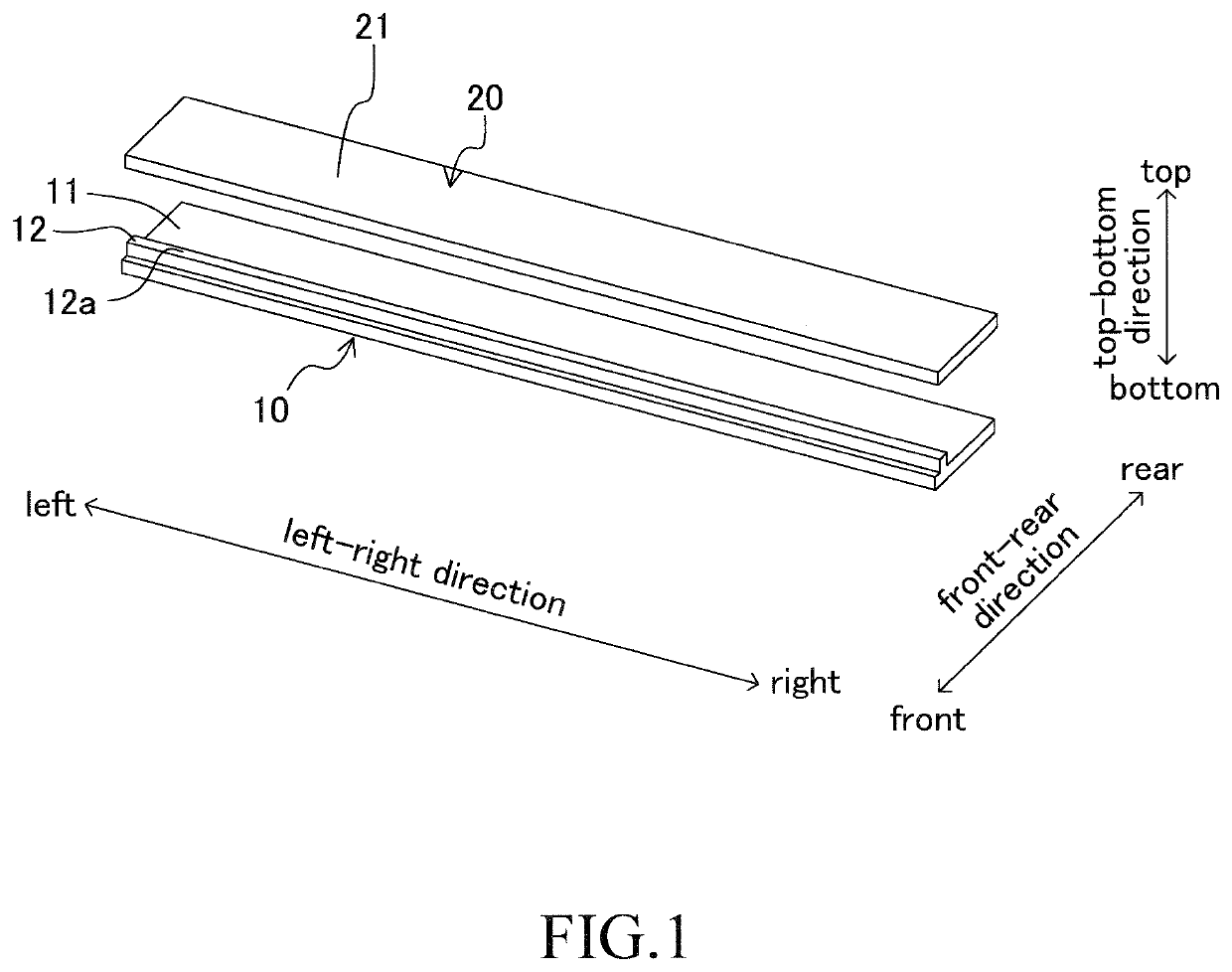
[0047]A synthetic resin member welding method according to an embodiment of the present invention will next be described. The present embodiment will be described while referring to an example of a method for forming an approximately plate-shaped component by welding together a first member 10 and a second member 20 each approximately having a plate shape as shown in FIG. 1. First, the structures of the first member 10 and the second member 20 will be described.

[0048]The first member 10 and the second member 20 are made of synthetic resin. Specifically, the first member 10 and the second member 20 are made of a carbon fiber reinforced plastic (CFRP). The first member 10 and the second member 20 have high laser light absorbency. That is, a laser beam hardly penetrates through the first member 10 and the second member 20. Also, the first member 10 and the second member 20 have high thermal conductivity. For example, when the first member 10 and the second member 20 contain carbon fibe...


PUM

PropertyMeasurementUnit
thermal conductivityaaaaaaaaaa
lengthaaaaaaaaaa
widthaaaaaaaaaa

Abstract

A protrusion on a first member made of synthetic resin wherein a laser beam is applied to a side surface of the protrusion in a state in which a top surface of the protrusion of the first member is abutted against a second member made of synthetic resin, so as to melt at least the entire top surface of the protrusion and melt a portion of the second member in contact with the protrusion by heat of the melted top surface of the protrusion, followed by solidification of the melted portions, whereby the first member and the second member are welded together.

Description

TECHNICAL FIELD[0001]The present invention relates to a method for welding synthetic resin members.BACKGROUND ART[0002]As described in the following Patent Documents 1 to 3, according to known methods for welding synthetic resin members, synthetic resin members (a first member and a second member) are abutted against each other, and abutting portions are irradiated with a laser beam to be melted, followed by solidification.[0003]According to Patent Document 1, a first member having high laser light transmittancy and a second member having high laser light absorbency (low laser light transmittancy) are stacked. A laser beam is applied from a first member side. The laser beam transmitting through the first member melts a surface of the second member (i.e., a surface in contact with the first member). The thus-melted synthetic resin material spreads between the first member and the second member. Subsequently, the synthetic resin material having spread between the first member and the ...

Claims


Application Information

Patent Timeline
Patent Type & Authority Patents(United States)
IPC IPC(8): B29C65/16B29K307/04
CPCB29C65/1648B29C65/1654B29K2307/04B23K26/324B29C66/114B29C66/112B29C66/8161B29C66/8322B29C66/81415B29C66/81463B29C66/5346B29C66/322B29C65/7829B29C66/223B29C66/7212B29C66/73921B29C66/43B29C65/1667B29C65/1629B29C65/1616B29C66/919B29C66/939B29C66/3034
Inventor MORI, TAKAYUKIHIROSAKI, KENICHIOKUMURA, WATARUMORI, DAISUKEIWANO, YOSHIHIROAMAOKA, KAZUAKI
Owner TOYOTA JIDOSHA KK
Why Eureka
Try Eureka