Bonding structure of electrical contact, bonding method of electrical contact and battery module

a technology of electrical contact and bonding structure, which is applied in the field of bonding structure of electrical contact, bonding method of electrical contact and battery module, can solve the problems of low welding speed, high defect rate of electrical contact, and limited selection of materials upon production, so as to reduce the phenomenon of overwelding in the bonding structure, reduce the overwelding phenomenon, and improve the stability

Pending Publication Date: 2021-12-30
SIMPLO TECH COMPANY
View PDF13 Cites 0 Cited by
  • Summary
  • Abstract
  • Description
  • Claims
  • Application Information

AI Technical Summary

Benefits of technology

[0006]An objective according to an embodiment of this disclosure is to provide a bonding structure of an electrical contact capable of reducing the over-welding phenomenon in the bonding structure, and a method of manufacturing the bonding structure of the electrical contact. An objective of another embodiment is to provide a battery module including bonding structures of electrical contacts fun

Problems solved by technology

However, the defective rate thereof is high.
For example, a sticky needle, empty welding and spot explosion may be formed, the welding speed is low, and the selections of the materials upon production are limited.
Regarding the soldering welding, the tin wire functions as the welding material for each welding spot, the tin resources and human resources are wasted, and the environment contamination is increased.
Furthermore, the soldering operation has the low speed.
When the production conditions are uncertain and the welding techniques and skills

Method used


Image

  • Bonding structure of electrical contact, bonding method of electrical contact and battery module
  • Bonding structure of electrical contact, bonding method of electrical contact and battery module
  • Bonding structure of electrical contact, bonding method of electrical contact and battery module

Examples


Embodiment Construction

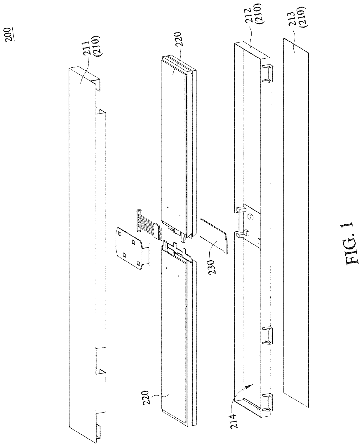
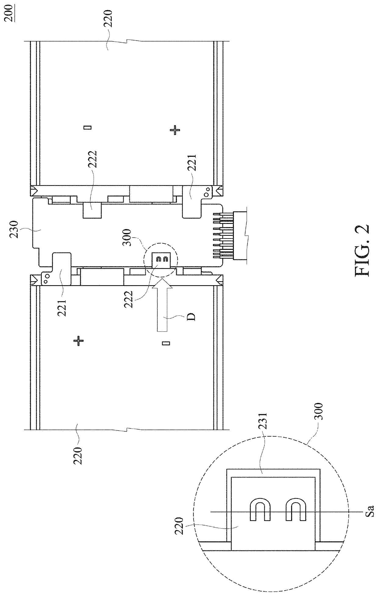
[0029]FIG. 1 is an exploded view showing a battery module of an embodiment of this disclosure. FIG. 2 is a plane view showing an internal partial structure of the battery module of the embodiment of FIG. 1. Referring to FIGS. 1 and 2, a battery module 200 according to an embodiment of this disclosure includes a housing 210, a bonding structure 300, at least one battery device 220 and a circuit carrier 230. The battery device 220 includes at least one battery cell. In one embodiment, there may be multiple battery cells, and each of the battery devices 220 has the battery cells connected in series and in parallel. The housing 210 defines a chamber 214 for accommodating the battery device 220 and the circuit carrier 230. As shown in FIG. 2, the battery device 220 is connected to the circuit carrier 230 through the bonding structure 300. The housing 210 includes a top cover 211, a bottom cover 213 and a frame 212. The frame 212 is disposed between the top cover 211 and the bottom cover ...


PUM

PropertyMeasurementUnit
Lengthaaaaaaaaaa
Lengthaaaaaaaaaa
Poweraaaaaaaaaa

Abstract

A bonding structure of an electrical contact, a bonding method of the electrical contact and a battery module are provided. The bonding structure of the electrical contact includes an electroconductive part and an electrode sheet welded to the electroconductive part. The electrode sheet is a first metal material, and the electroconductive part is a second metal material. A welding track is formed on an interface formed by combining the electrode sheet with the electroconductive part. The welding track is a mixture of the first metal material and the second metal material. The welding track substantially has no overlap. In addition, the welding track includes a moving path, and a lateral path of performing a wobble movement or an oscillation movement on lateral sides of the moving path.

Description

CROSS-REFERENCE TO RELATED APPLICATIONS[0001]This application claims priority of No. 109121656 filed in Taiwan R.O.C. on 2020 / 6 / 24 and No. 110106196 filed in Taiwan R.O.C. on 2021 / 2 / 22 under 35 USC 119, the entire content of which is hereby incorporated by reference.BACKGROUND OF THE INVENTIONField of the Invention[0002]This disclosure relates to a bonding structure of an electrical contact, a bonding method of the electrical contact and a battery module including the bonding structure of the electrical contact, and more particularly to a bonding structure of an electrical contact having two different materials, wherein the bonding structure has a continuous welding track.Description of the Related Art[0003]According to the prior art, Taiwan Patent No. M285125 discloses a battery module, in which different materials of metallic conductive sheets are disposed between battery cells or circuit substrates, and the battery cells are bonded in parallel or in series by way of resistance we...

Claims


Application Information

Patent Timeline
IPC IPC(8): H01M50/516H01M50/103H01M50/557H01M10/0585
CPCH01M50/516H01M10/0585H01M50/557H01M50/103H01M10/0525H01G11/06H01G11/10H01G11/66H05K3/328H05K2201/10037H05K2203/107H05K2201/09263B23K26/28H01L21/4853B23K26/244B23K26/082B23K2101/36B23K2103/10B23K2103/12Y02E60/10Y02P70/50B23K26/323B23K26/32B23K26/0876
Inventor WU, YU-WENWU, SHANG-HSIENWANG, CHUN-YAO
Owner SIMPLO TECH COMPANY
Why Eureka
Try Eureka