Manufacturing method for joined body, welding metal body, and joining element
a manufacturing method and metal body technology, applied in the direction of manufacturing tools, soldering devices, auxillary welding devices, etc., can solve the problems of increasing a number of operation processes or costs, and achieve the effect of facilitating heat transfer from the joining element to the non-ferrous metal material, and enhancing the welding strength between the joining element and the mating member
- Summary
- Abstract
- Description
- Claims
- Application Information
AI Technical Summary
Benefits of technology
Problems solved by technology
Method used
Image
Examples
second embodiment
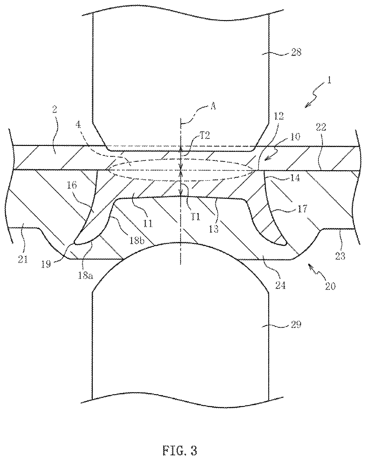
[0073]FIG. 4A is a cross-sectional view of the joining element 30 in the FIG. 4B is a cross-sectional view of a joined body 40 obtained by joining a mating member 2 and a non-ferrous metal material 42 with each other via the joining element 30. In FIG. 4B, a representation of an indentation caused by the electrodes 28, 29 (refer to FIG. 3) is omitted.
[0074]As shown in FIG. 4A, the joining element 30 includes the disk-shaped body portion 31 and the cylindrical leg portion 34 protruded from the body portion 31 and these portions are integrally formed of low-carbon steel with a carbon content of 0.4 mass % or less. The joining element 30 is formed in axial symmetry with respect to the virtual axis A. FIG. 4A and FIG. 4B show a cross section including the virtual axis A.
[0075]The body portion 31 includes: a joining surface 12; a back surface 13 located on the opposite side to the joining surface 12; and an outer peripheral surface continuing to an outer peripheral edge of the joining s...
first embodiment
[0077]As shown in FIG. 4B, the joining element 30 is press-fitted into the non-ferrous metal material 42 to form a welding metal body 41 and a melted portion 4 is formed between the joining element 30 of the welding metal body 41 and the mating member 2 by welding. Thus, the joined body 40 is manufactured. The non-ferrous metal material 42 is identical with the non-ferrous metal material 21 in configuration except that the non-ferrous metal material is formed thicker than the non-ferrous metal material 21 in the A thickness of the non-ferrous metal material 42 is two or more times a dimension of the section from the joining surface 12 to the tip 37 of the joining element 30 in the direction of the virtual axis A. For this reason, even when the joining element 30 is press-fitted into the non-ferrous metal material 42, the back surface 23 of the non-ferrous metal material 42 hardly swells.
[0078]Since the inner circumferential surface 36 of the leg portion 34 prior to press-fitting sh...
third embodiment
[0081]FIG. 5 is a cross-sectional view of the joined body 50 in the In FIG. 5, a representation of an indentation caused by the electrodes 28, 29 (refer to FIG. 3) is omitted. The joined body 50 includes the mating member 2 and a welding metal body 51 obtained by press-fitting the joining element 52 into the non-ferrous metal material 42. By welding the mating member 2 to the joining element 52 of the welding metal body 51 to form a melted portion 4, the joined body 50 is manufactured.
[0082]The joining element 52 includes a disk-shaped body portion 11 and a cylindrical leg portion 54 protruded from the periphery side of the back surface 13 of the body portion 11 and these portions are integrally formed of low-carbon steel with a carbon content of 0.4 mass % or less. The joining element 52 is formed in axial symmetry with respect to a virtual axis A. FIG. 5 shows a cross section including the virtual axis A.
[0083]The inner circumferential surface 58 of the leg portion 54 is formed i...
PUM
| Property | Measurement | Unit |
|---|---|---|
| angle | aaaaa | aaaaa |
| angle of inclination | aaaaa | aaaaa |
| diameter | aaaaa | aaaaa |
Abstract
Description
Claims
Application Information
 - R&D
- Intellectual Property
- Life Sciences
- Materials
- Tech Scout
- Unparalleled Data Quality
- Higher Quality Content
- 60% Fewer Hallucinations
Browse by: Latest US Patents, China's latest patents, Technical Efficacy Thesaurus, Application Domain, Technology Topic, Popular Technical Reports.
© 2025 PatSnap. All rights reserved.Legal|Privacy policy|Modern Slavery Act Transparency Statement|Sitemap|About US| Contact US: help@patsnap.com


