Sliding member

a technology of sliding member and carbon fiber, which is applied in the direction of sliding contact bearings, mechanical equipment, rotary machine parts, etc., can solve the problems of excessive damage to the counter shaft, and achieve the effects of improving the strength of the sliding layer, accelerating abrasive wear, and high hardness of carbon fibers

Active Publication Date: 2022-02-01
DAIDO METAL CO LTD
View PDF21 Cites 2 Cited by
  • Summary
  • Abstract
  • Description
  • Claims
  • Application Information

AI Technical Summary

Benefits of technology

[0003]The dispersion of carbon fibers in a synthetic resin has advantages in that high hardness of the carbon fibers improves wear resistance and that a fibrous shape of the carbon fibers improves strength of a sliding layer made of the synthetic resin. However, in some cases, excessively high hardness of the carbon fibers damages a counter shaft. Furthermore, there are following problem. Even when the synthetic resin matrix is worn, the carbon fibers are not worn. Thus, when the synthetic resin matrix is further worn, the carbon fibers protrude from a sliding surface of the sliding layer, and the carbon fibers fall off from the synthetic resin. The carbon fibers that have fallen off from the synthetic resin enter the space between the sliding surface and the counter shaft to accelerate abrasive wear.
[0004]Therefore, an object of the present invention is to solve the above problem of the conventional technique and to provide a sliding member in which fibrous particles are appropriately worn, thereby providing a sliding member that includes a sliding layer having higher wear resistance and is less likely to damage a counter shaft.

Problems solved by technology

However, in some cases, excessively high hardness of the carbon fibers damages a counter shaft.

Method used


Image

  • Sliding member
  • Sliding member

Examples


examples

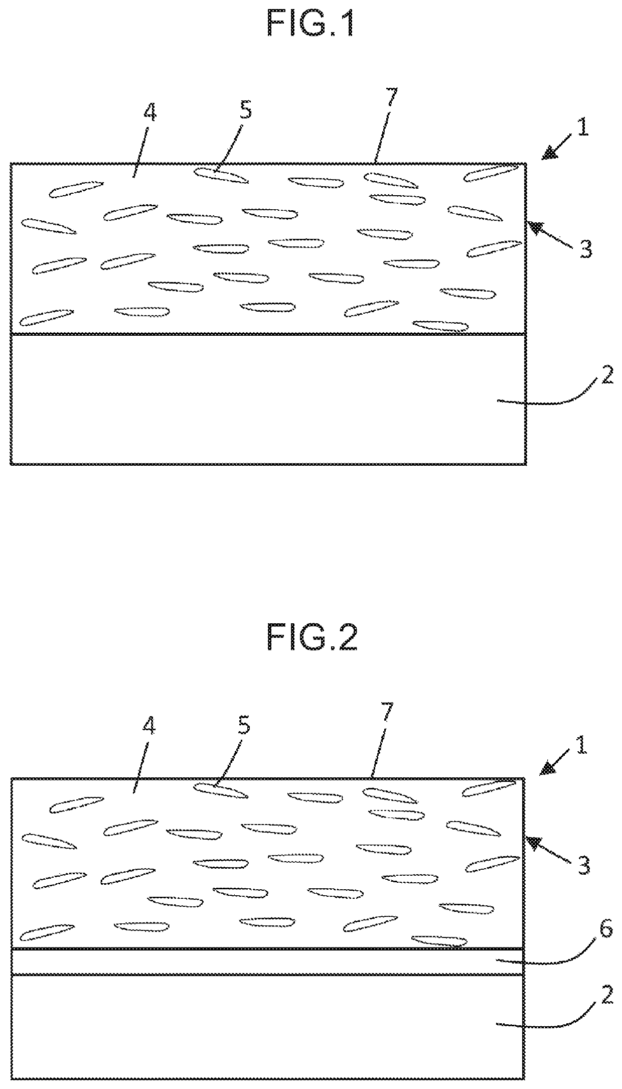
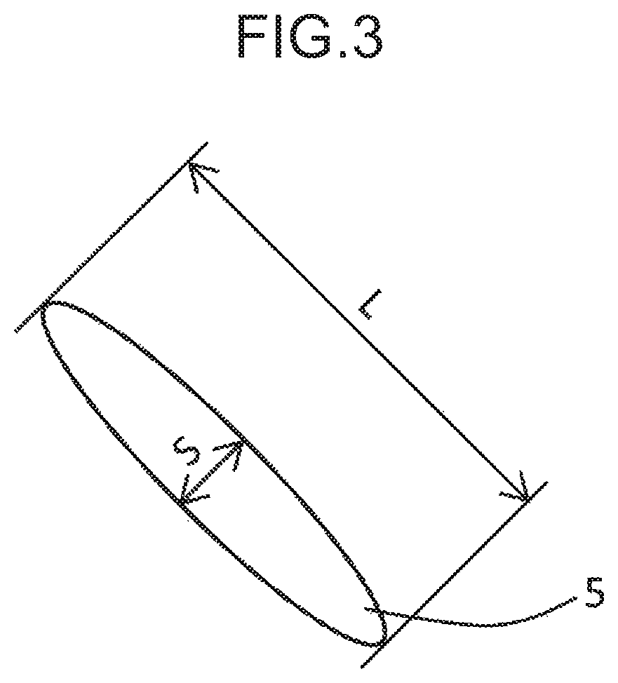
[0053]Examples 1 to 9 of the sliding member including the back-metal layer and the sliding layer according to the present invention and Comparative Examples 10 to 17 were produced in the following manner. Table 1 shows composition of the sliding layer of the sliding members of Examples 1 to 9 and Comparative Examples 10 to 17. In Table 1, a column “Synthetic resin” shows a volume ratio of PTFE, PEEK and PVF in the synthetic resin, and a column “Additives” shows a volume ratio of each additive in the entire sliding layer.

[0054]

TABLE 1Measured values ofSliding layer composition (volume %)fibrous particlesAdditives**NanoSemi-Car-Spher-IndenterAverageEvaluationGraphitebonicalSolidHard-AverageGrainPresence ofAmountSynthetic resin*FibrousFiberGraphitelubricantFillernessAspectSizedamage toof wearPTFEPEEKPVFparticlesparticlesparticlesMoS2WS2CaCO3(MPa)ratio(μm)shaft(μm)Exam-1100——1—————1000 525Not present11.9ples299——3—————15001550Not present11.13100——5—————20002025Not present7.44100——10————...


PUM

PropertyMeasurementUnit
aspect ratioaaaaaaaaaa
grain sizeaaaaaaaaaa
volume %aaaaaaaaaa

Abstract

A sliding member includes a back-metal layer and a sliding layer on the back-metal layer, and the sliding layer has a sliding surface. The sliding layer includes a synthetic resin and fibrous particles dispersed in the synthetic resin. A volume ratio of the fibrous particles in the sliding layer is 1 to 15%, and the fibrous particles are made of semi-graphite having a nano indenter hardness of 1000 to 5000 MPa. An average aspect ratio of the fibrous particles is not less than 5, where an aspect ratio is defined as a ratio of a major axis to a minor axis of the fibrous particle viewed from the sliding surface. An average grain size of the fibrous particles in cross-sectional view perpendicular to the sliding surface is 5 to 50 μm.

Description

TECHNICAL FIELD[0001]The present invention relates to a sliding member, and specifically relates to a sliding member including a back-metal layer and a sliding layer made of a synthetic resin.RELATED ART[0002]A sliding member which includes a back-metal layer made of a metal and a sliding layer made of a resin composition coated on the back-metal layer has been used in a bearing or the like. Such resin composition for the sliding member has been known that incudes carbon fiber particles dispersed in a synthetic resin to improve wear resistance and strength of the sliding layer (see, for example, JP 10-204282A and JP 2013-194204A). The resin composition including carbon fiber particles dispersed in a synthetic resin has been also proposed for a multilayer bearing in which a porous layer is formed on a steel plate or the like and the porous layer is impregnated and coated with a resin composition including a synthetic resin such as PTFE. For example, carbon fibers are dispersed in a s...

Claims


Application Information

Patent Timeline
Patent Type & Authority Patents(United States)
IPC IPC(8): F16C17/02F16C33/12F16C33/20
CPCF16C33/201F16C17/022F16C33/122F16C33/206F16C2208/02F16C2208/32F16C2208/86F16C33/24F16C2208/58F16C2208/42F16C2208/40F16C2208/44F16C2208/60F16C2208/66F16C2208/36F16C2208/78F16C2208/52F16C33/205F16C2206/06F16C2240/48F16C2202/52
Inventor ITO, YOSHIFUMISUZUKI, YUYAMAUCHI, TAKAYOSHI
Owner DAIDO METAL CO LTD
Why Eureka
Try Eureka