Reduced footprint collimator device to focus light beam over length of optical path

a collimator device and light beam technology, applied in the field of flow cytometry applications, can solve the problems of limiting reducing the overall instrument size, so as to achieve the effect of reducing the number of receptors, reducing the beam power at the receptor, and reducing the footprin

Active Publication Date: 2022-02-15
MACCAL CO INC
View PDF8 Cites 0 Cited by
  • Summary
  • Abstract
  • Description
  • Claims
  • Application Information

AI Technical Summary

Benefits of technology

[0004]A fiber cable typically has a minimum bend radius of approximately six inches. This required bend radius forces a much larger footprint which makes the overall instrument larger or limits the number of receptors.
[0005]An objective is to provide a Reduced Footprint Collimator Device To Focus Light Beam Over Length Of Optical Path that maintains the beam power while redirecting the beam along a path perpendicular to the incoming beam. The fiber cable now enters perpendicular to the photoreceptor subsystem This gives more room for the minimum fiber bend radius and allows a reduction in the overall footprint of the beam path.
[0006]Another objective is to provide a Reduced Footprint Collimator Device To Focus Light Beam Over Length Of Optical Path that allows simple alignment of the optical beam with the receiving photomultipliers.
[0010]The invention generally relates to an optical beam collimator which includes a reduced footprint 90 degree collimator which allows light beam collimation, beam path alignment, selectable beam focal distance, and reduces stray light reflections all in a minimal footprint. This feature allows for a smaller overall instrument design.
[0014]Another objective is to provide a Reduced Footprint Collimator Device To Focus Light Beam Over Length Of Optical Path that maintains the beam power while redirecting the beam along a path perpendicular to the incoming beam. This allows a reduction in the overall footprint of the beam path.
[0015]Another object is to provide a Reduced Footprint Collimator Device To Focus Light Beam Over Length Of Optical Path that allows simple alignment of the optical beam with the receiving photomultipliers.

Problems solved by technology

The problem is that the farther the photomultiplier is from the laser source the lower the beam power is at the receptor.
This required bend radius forces a much larger footprint which makes the overall instrument larger or limits the number of receptors.

Method used


Image

  • Reduced footprint collimator device to focus light beam over length of optical path
  • Reduced footprint collimator device to focus light beam over length of optical path
  • Reduced footprint collimator device to focus light beam over length of optical path

Examples


Embodiment Construction

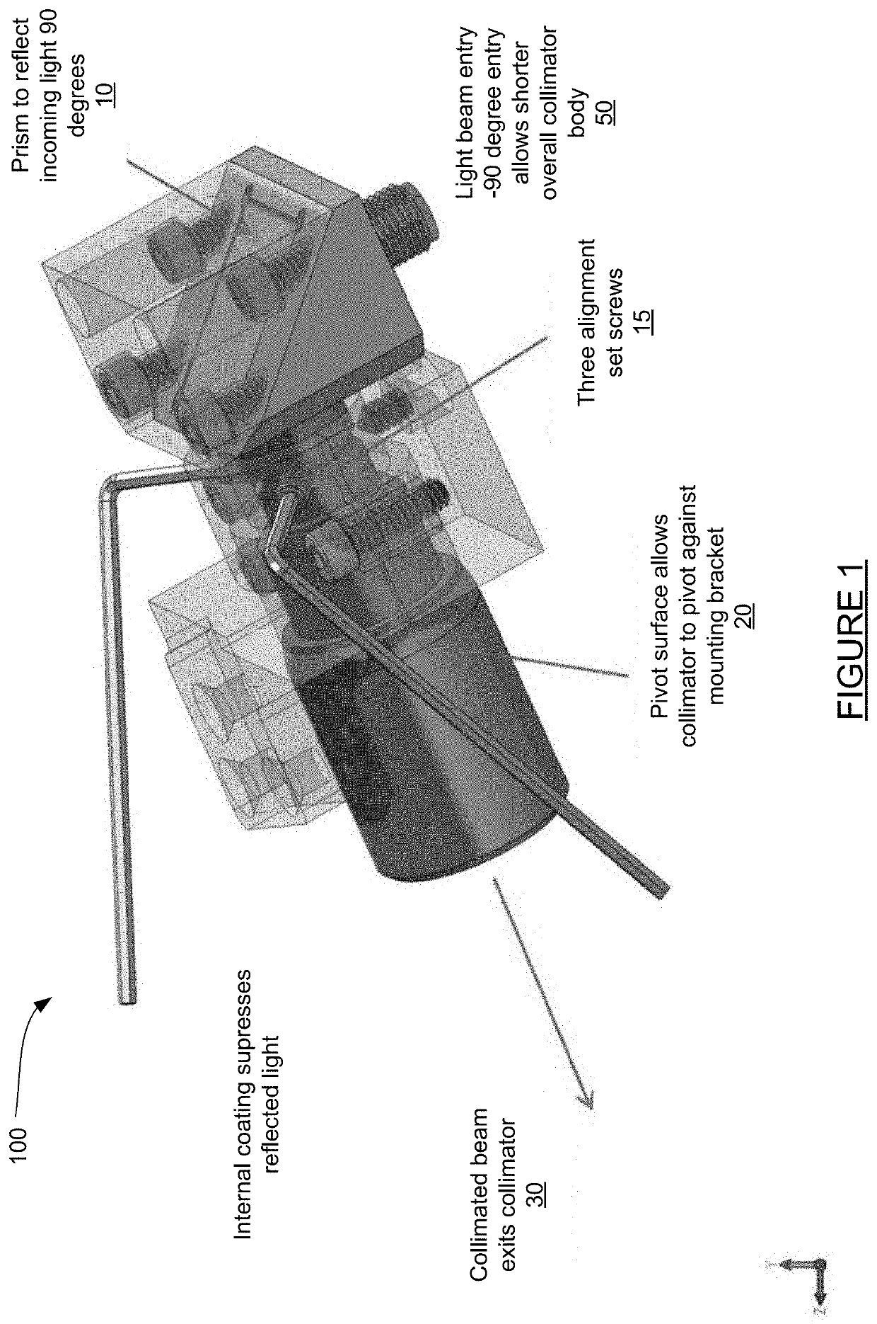
[0025]FIG. 1, depicting an collimator assembly 100, includes a prism 10 to reflect incoming light 90 degrees, three alignment set screws 15, a fillet surface 20 which allows a collimator to pivot against a mounting bracket, a collimated beam 30 that exits the collimator, and a light beam entry 50 having a −90 degree entry that allows for a shorter overall collimator body.

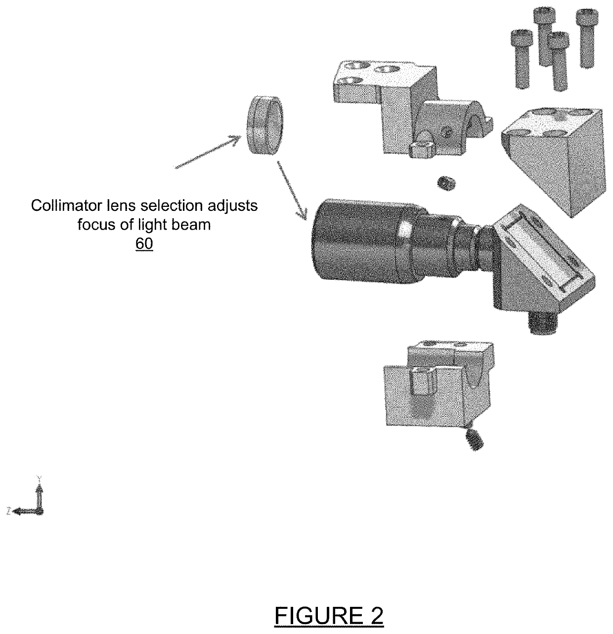
[0026]FIG. 2 is a right exploded view of a collimator assembly showing assembly of the various components of the collimator. FIG. 2 includes a collimator lens selection 60 that adjusts the focus of a light beam.

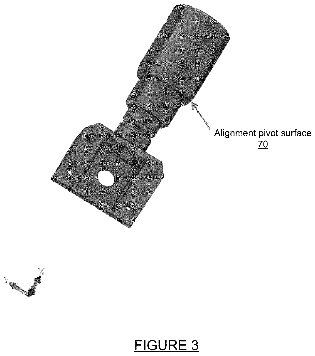
[0027]FIG. 3 is a top partial view of a collimator gimbal surface used for adjustment and mounting of the prism / mirror. The gimbal surface includes an alignment pivot surface 70.

[0028]FIG. 4 is a left section view of a collimator showing surfaces treated with anti-reflective coating. The collimator of FIG. includes an anti-reflective coating 80 on internal surfaces.

[0029]Since other modifications and changes ...


PUM

PropertyMeasurementUnit
bend radiusaaaaaaaaaa
lengthaaaaaaaaaa
diameteraaaaaaaaaa

Abstract

A reduced footprint collimator device to focus light beam over length of optical path for use in an optical cytometry device or other optical instrument where a focused beam of light is passed through a test medium and then sampled by a photomultiplier or multiple photomultipliers for analysis. This device provides alignment and focus of that beam and collimation along the entire beam path. In addition in order to reduce the overall footprint of the beam path this device uses a precision coated prism to redirect the optical path perpendicular to the entering optical beam. The reduced footprint collimator device to focus light beam over length of optical path generally includes a reduced footprint 90 degree collimator which allows light beam collimation, beam path alignment, selectable beam focal distance, and reduces stray light reflections all in a minimal footprint.an These features allows for a smaller overall instrument design.

Description

RELATED APPLICATIONS[0001]The present application is a continuation application of U.S. provisional patent application Ser. No. 62 / 179,578, filed May 2, 2016, for REDUCED FOOTPRINT COLLIMATOR DEVICE TO FOCUS LIGHT BEAM OVER LENGTH OF OPTICAL PATH, by Robert Duncan, Michael Hall, James Nguyen, included by reference herein and for which benefit of the priority date is hereby claimed.FIELD OF THE INVENTIONBackground of the Invention[0002]For flow cytometry applications, laser beams of various wavelengths of light are directed through a chamber filled with the sample to be tested. The samples absorb some wavelengths while passing others. The laser beams which are not absorbed pass out of the chamber and typically are directed into a fiber optic cable for connection to a device which directs the beams through various filters into photo receptors (photomultipliers) which convert the light signals into electrical signals for computer analysis. The problem is that the farther the photomulti...

Claims


Application Information

Patent Timeline
Patent Type & Authority Patents(United States)
IPC IPC(8): G02B27/30G02B1/11G01N15/14
CPCG02B27/30G02B1/11G01N15/1434G01N15/1459
Inventor DUNCAN, ROBERTHALL, MICHAELNGUYEN, JAMES
Owner MACCAL CO INC
Why Eureka
Try Eureka