Control circuit and control method for power converter

a control circuit and converter technology, applied in the direction of electric variable regulation, process and machine control, instruments, etc., can solve the problem of no solution proposed for the current sharing between multiple converter sets, and achieve the effect of optimizing the overall efficiency of the power converter

Active Publication Date: 2022-03-01
NAT TAIWAN UNIV OF SCI & TECH
View PDF31 Cites 0 Cited by
  • Summary
  • Abstract
  • Description
  • Claims
  • Application Information

AI Technical Summary

Benefits of technology

[0013]Therefore, the control circuit and the control method for the power converter provided by the present disclosure can enable rectifier switches of a power converter that has multiple sets of rectification paths to determine on-times individually through the zero current detection circuits. The control circuit and the control method provided by the present disclosure can not only overcome differences in on-times of the rectifier switches caused by the component error of each individual rectifier loop, but can also achieve functions of zero voltage turned on and zero current turned off for each of the rectifier components, thereby optimizing an overall efficiency of the power converter.

Problems solved by technology

However, in parallel applications, no solution is proposed for the current sharing between multiple sets of converters.
Therefore, one of the important issues in the art is how to improve a control mechanism to retain existing automatic adjustment of on-time control, such that an overall converter can be optimized in terms of efficiency, with the output voltage and output impedance being adjustable, and parallel outputs can be balanced.

Method used


Image

  • Control circuit and control method for power converter
  • Control circuit and control method for power converter
  • Control circuit and control method for power converter

Examples


first embodiment

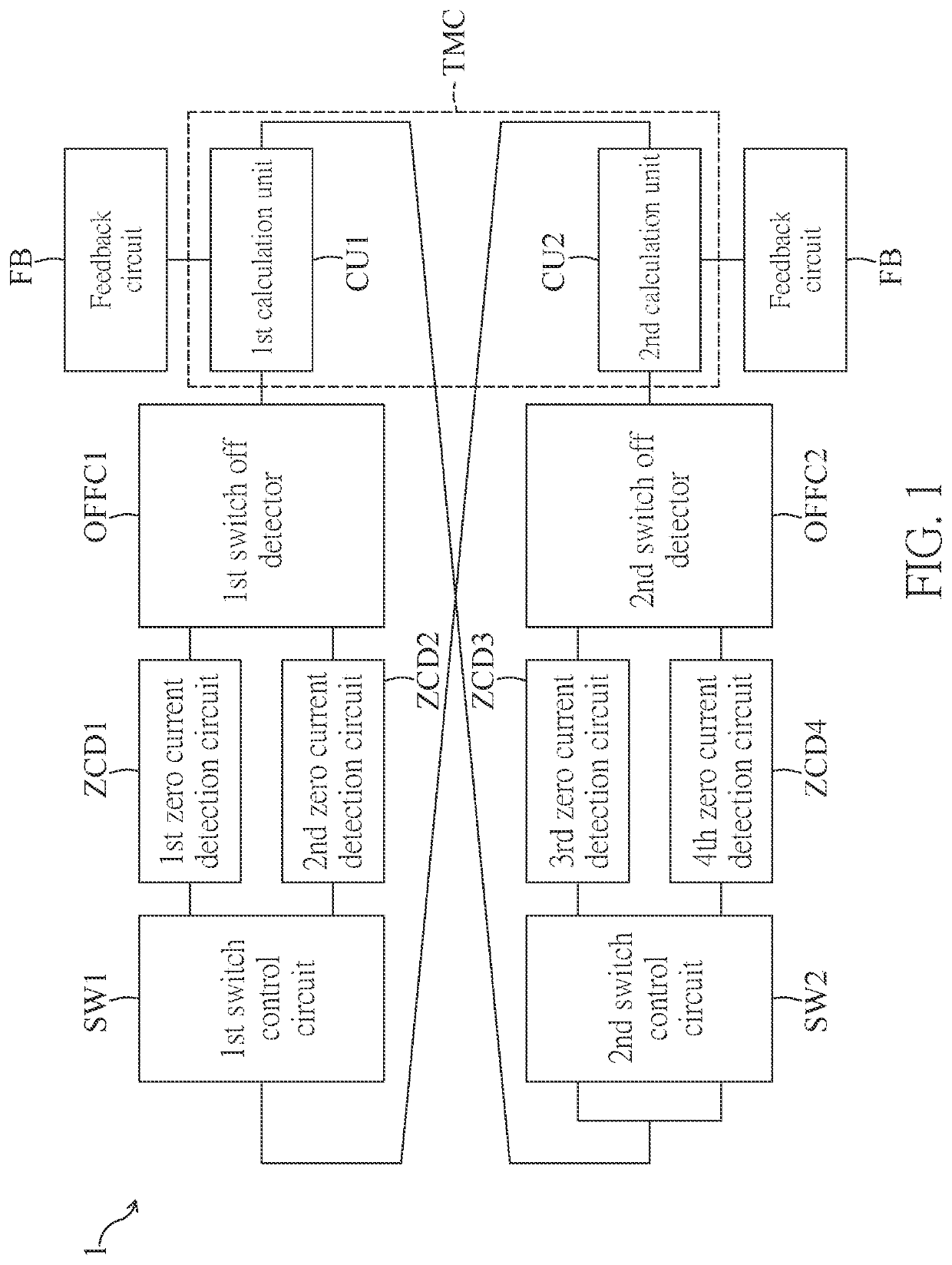
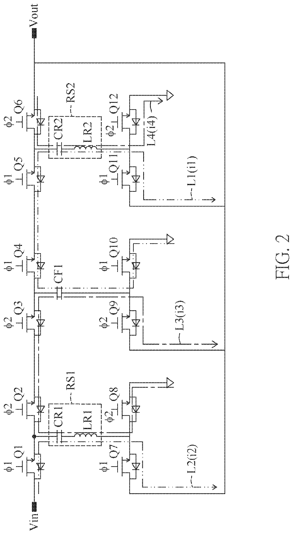
[0025]FIG. 1 is a functional block diagram of a control circuit for a power converter according to a first embodiment of the present disclosure. Referring to FIG. 1, the first embodiment of the present disclosure provides a control circuit for a power converter, and further reference can be made to FIG. 2, which is a circuit layout of the power converter according to the first embodiment of the present disclosure. As shown in FIG. 2, the power converter can be a switched tank converter (STC), which includes resonant tanks RS1 and RS2 and switches Q1 to Q12 provided between an input terminal Vin and an output terminal Vout. The switches Q1 to Q12 can respectively correspond to a first mode Φ1 and a second mode Φ2, and the input terminal Vin receives an input voltage. The resonant tank RS1 can include a resonant capacitor CR1 and a resonant inductor LR1. The resonant tank RS2 can include a resonant capacitor CR2 and a resonant inductor LR2. A non-resonant capacitor CF1 is separate fro...

second embodiment

[0047]Reference is further made to FIG. 4, which is a functional block diagram of a control circuit for a power converter according to a second embodiment of the present disclosure. As shown in FIG. 4, the elements of this embodiment are basically similar to those of FIG. 1, so that part of the repeated description will be omitted. The difference is that the modulation time calculation module TMC of this embodiment includes a third calculation unit CU3 and a phase shifter PS. The following is a description with reference to FIGS. 5 and 6. FIG. 5 is a circuit layout of a power converter according to the second embodiment of the present disclosure, and FIG. 6 is a switch timing diagram according to the second embodiment of the present disclosure.

[0048]As shown in FIG. 5, the power converter can be a resonant switched capacitor converter (ReSC), which includes a two-stage resonant tank and switches Q1′ to Q8′ arranged between an input terminal Vin and an output terminal Vout, and an ou...


PUM


Abstract

A control circuit and a control method for a power converter are provided. The power converter includes a plurality of resonant tanks and a plurality of switches disposed between an input terminal and an output terminal. The switches correspond to a first mode and a second mode, respectively, and the control circuit includes a first switch control circuit, a first zero current detection circuit, a second zero current detection circuit, a first switch off detector, a modulation time calculation module, a second switch control circuit, a third zero current detection circuit, a fourth zero current detection circuit, and a second switch off detector. The control circuit uses a plurality of zero current detection circuits to perform time modulations on a plurality of rectifier switches in the switches.

Description

CROSS-REFERENCE TO RELATED PATENT APPLICATION[0001]This application claims the benefit of priority to Taiwan Patent Application No. 109128519, filed on Aug. 21, 2020. The entire content of the above identified application is incorporated herein by reference.[0002]Some references, which may include patents, patent applications and various publications, may be cited and discussed in the description of this disclosure. The citation and / or discussion of such references is provided merely to clarify the description of the present disclosure and is not an admission that any such reference is “prior art” to the disclosure described herein. All references cited and discussed in this specification are incorporated herein by reference in their entireties and to the same extent as if each reference was individually incorporated by reference.FIELD OF THE DISCLOSURE[0003]The present disclosure relates to a control circuit and a control method, and more particularly to a control circuit and a con...

Claims


Application Information

Patent Timeline
Patent Type & Authority Patents(United States)
IPC IPC(8): H02M1/08H02M7/217H02M3/00H02M1/00H02M3/158H02M3/07
CPCH02M1/083H02M3/01H02M7/217H02M1/0009H02M1/0048H02M1/0058H02M3/07H02M3/1588H02M3/158H02M3/04H02M1/0095Y02B70/10
Inventor HUANG, CHIEN-CHUNCHIU, HUANG-JEN
Owner NAT TAIWAN UNIV OF SCI & TECH
Why Eureka
Try Eureka