
Device and method for determining a volume of projection of a dual-axis computed tomography system

a computed tomography and volume measurement technology, applied in the field of devices and methods for determining the volume of projection of a dual-axis computed tomography system, can solve the problems of only mathematically exact reconstructions of this trajectory, and the size and shape of the projection volume is increasingly difficult to estimate in advance, so as to improve the insight of the projection volum

Active Publication Date: 2022-03-08
KONINKLJIJKE PHILIPS NV
View PDF9 Cites 0 Cited by
  • Summary
  • Abstract
  • Description
  • Claims
  • Application Information

AI Technical Summary

Benefits of technology

[0007]There may thus be a need to provide a device or a method that provides improved insight in the volume of projection of a dual-axis trajectory acquisition.
[0012]Furthermore, the field of view of an X-ray image may be refined using shutters at the X-ray tube. For example, horizontal shutters may be applied to the top and bottom of an image, such that a smaller part of an object of interest is imaged. Applying shutters may be useful for limiting an X-ray dose to be applied. In particular, it may be useful to limit or prevent X-ray dose to organs that are very sensitive to radiation, such as the thyroid gland when acquiring a head scan. It also may improve image quality due to less X-ray scatter. Applying these shutters to a dual-axis scan, however, may have an unforeseen large effect to the volume of projection. A larger than anticipated part of an object of interest may not be imaged due to the difficult predictable volume of projection of a dual-axis trajectory.
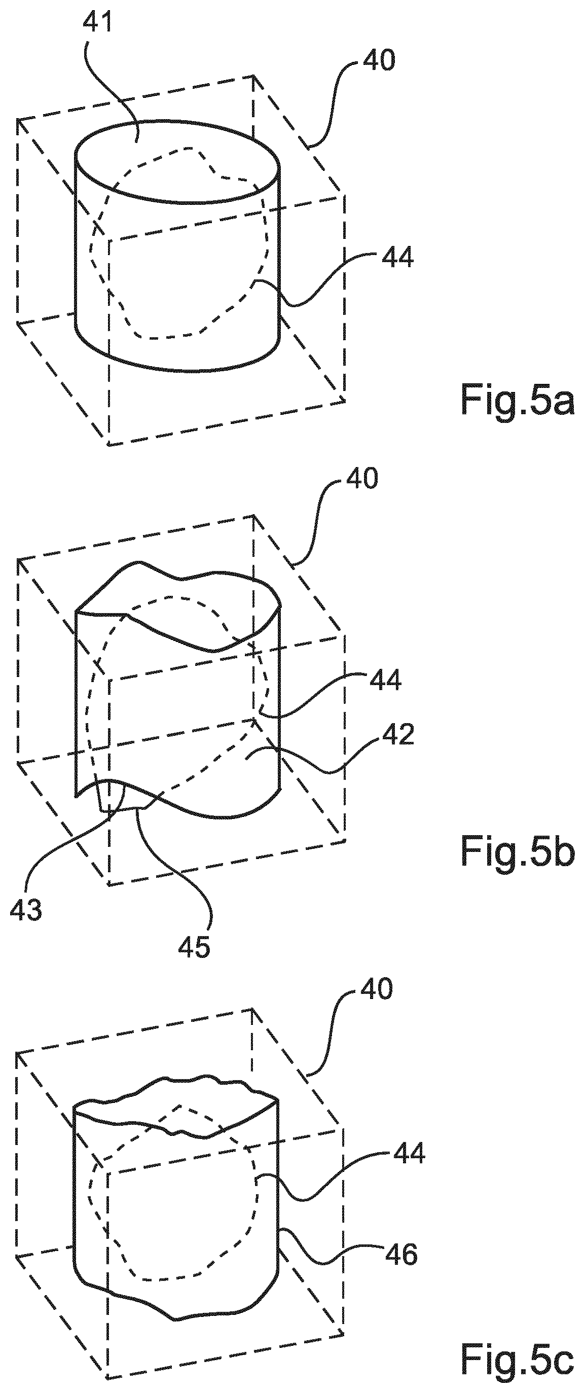
[0013]With the invention, a user may select a volume of interest in the object of interest. That selection may for example be performed by overlaying a reconstruction cylinder or cube on a pre-determined image of the object of interest. In an example, that pre-determined image may be a fluoroscopy image. The interface unit may receive the selected volume of interest. In an exemplary embodiment, the interface unit may receive the volume of interest by direct input from the user. In another exemplary embodiment, the volume of interest receives a signal created by another device which interacts with the user. The projection module then simulates a volume of projection of the detector wherein the detector is moved along the dual-axis trajectory of a dual-axis computed tomography system. While the projection module determines the volume of projection, the position determination module may simulate different shutter positions for the dual-axis computed tomography system. The position determination module adapts those simulated shutter positions for each detector position by variation such that the determined volume of projection covers the volume of interest being received by the interface unit. The volume of projection is therefore known in advance to the actual image process and the shutter positions are varied to provide a volume of projection which covers the volume of interest being indicated by the user. The volume of projection which is rather unpredictable for a user is therefore simulated first to ensure that the volume of interest occurs in the volume of projection when it is acquired by a dual-axis computed tomography imaging system. Thus, the present invention avoids that parts of an object of interest are unintentionally not imaged in dual-axis computed tomography imaging. Furthermore, the invention provides improved insight in the volume of projection of a dual-axis trajectory acquisition.
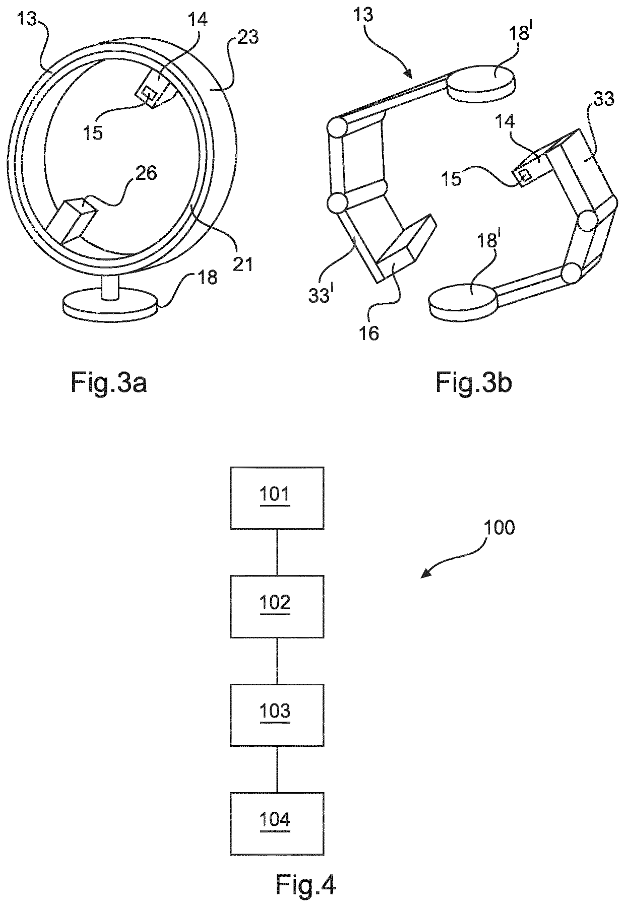
[0018]The shutter control element therefore may adjust at least one shutter of a dual-axis computed tomography system while the detector moves along the dual-axis trajectory. For each position of the detector on the dual-axis trajectory the shutter control element may adjust the shutter according to the shutter positions determined by the position determination module of the device. The shutter control element therefore ensures that the determined shutter positions are provided during the actual image acquisition with the dual-axis computed tomography system.
[0022]The suggestion module may therefore amend the pre-determined dual-axis trajectory of the detector. If the current pre-determined dual-axis trajectory does not provide a simulated volume of projection covering the complete volume of interest when adjusting the simulated shutters, the suggestion module may provide another dual-axis trajectory from a database which may provide a volume of projection covering the complete volume of interest when adjusting the shutters. Therefore, the suggestion module increases the number of volumes of projection which may be simulated for a dual-axis computed tomography system before image acquisition.
[0028]The dual-axis computed tomography system comprising a device according to the description above avoids that the volume of projection does not cover the volume of interest being chosen by the user before starting the imaging process. Prior to the actual image acquisition with the dual-axis computed tomography system, the device determines the shutter positions for each detector position such that the volume of projection will cover the volume of interest.

Problems solved by technology

However, reconstructions from this trajectory are only mathematically exact in the central plane, and suffer from artifacts outside this plane.
When a dual-axis trajectory is used instead of a planar circular trajectory, the size and shape of the volume of projection is increasingly difficult to estimate in advance, particularly for cone-beam computed tomography (CBCT) systems.

Method used


Image

  • Device and method for determining a volume of projection of a dual-axis computed tomography system
  • Device and method for determining a volume of projection of a dual-axis computed tomography system
  • Device and method for determining a volume of projection of a dual-axis computed tomography system

Examples


Embodiment Construction

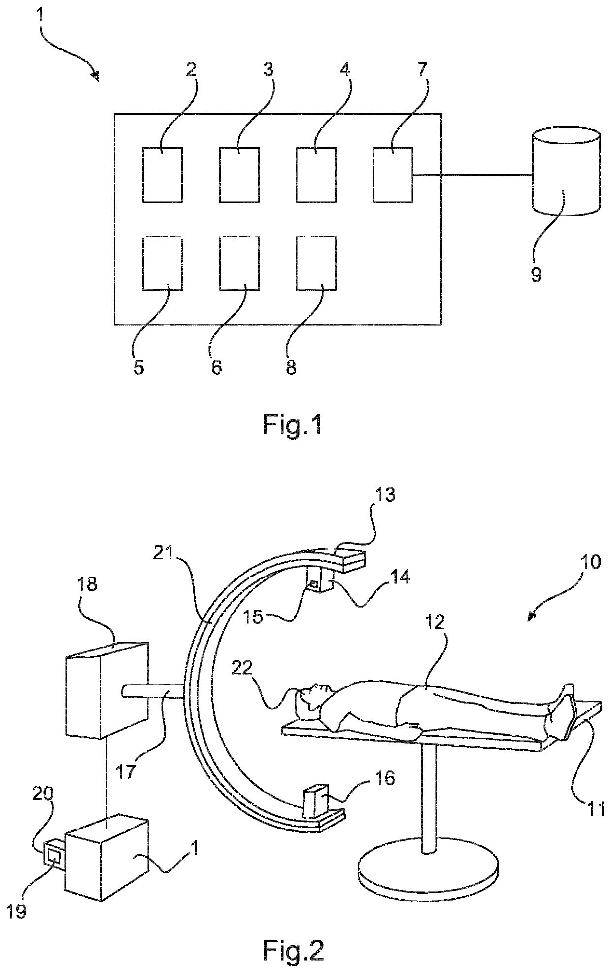
[0047]FIG. 1 shows a device for determining a volume of projection for a detector of a dual-axis computed tomography system with at least one shutter. The device is referenced with reference number 1.

[0048]The device 1 comprises an interface unit 2, a projection module 3, a position determination module 4, a shutter control element 5, a feedback module 6, a suggestion module 7, and a splitting module 8.

[0049]The interface module 2 may receive a volume of interest 44 for a computed tomography image showing an object 22. The volume of interest 44 may be chosen by a user by marking a region in a previously acquired image of the object of interest 22. The chosen region may be received by the interface module 2 and may be called the volume of interest 44. The volume of interest 44 may be the whole object of interest 22 or a part of the object of interest 22.

[0050]Furthermore, in an exemplary embodiment, the interface module 2 may receive the volume of interest 44 directly from the user b...


PUM


Abstract

The present invention relates to a device for determining a volume of projection of a dual-axis computed tomography system with at least one shutter, the device (1) comprising: an interface unit (2); a projection module (3); and a position determination module (4); wherein the interface unit (2) is configured to receive a volume of interest (44) for a computed tomography image showing an object (22); wherein the projection module (3) is configured to determine a volume of projection (41, 42, 46) of a detector (16) based on different simulated positions of the detector (16) on a trajectory around the object (22) and based on a variable simulated position of at least one shutter (15); and wherein the position determination module (4) is configured to determine the simulated position of the at least one shutter (15) for each determined simulated position of the detector (16) such that the volume of projection (41, 42, 46) corresponds to the volume of interest (44). The present invention avoids that parts of an object of interest are unintentionally not imaged in dual-axis computed tomography imaging whilst reducing x-ray absorption to parts of the object outside the volume of interest (44) and provides improved insight in the volume of projection (41, 42, 46) of a dual-axis trajectory acquisition.

Description

CROSS-REFERENCE TO PRIOR APPLICATIONS[0001]This application is the U.S. National Phase application under 35 U.S.C. § 371 of International Application No.PCT / EP2018 / 075131, filed on Sep. 18, 2018 which claims the benefit of European Patent Application No. 17193169.4, filed on Sep. 26, 2017, filed on. These applications are hereby incorporated by reference herein.FIELD OF THE INVENTION[0002]The present invention relates to a device and a method for determining a volume of projection of a dual-axis computed tomography system with at least one shutter.BACKGROUND OF THE INVENTION[0003]Modern angiography systems have the possibility to acquire computed tomography images (CT-images) next to their traditional two-dimensional (2-D) functionality. The CT-functionality is implemented by letting the X-ray source and detector rotate around an object of interest, during which a sequence of images is acquired. From these images a volume is reconstructed using a reconstruction algorithm. The volume...

Claims


Application Information

Patent Timeline
Patent Type & Authority Patents(United States)
IPC IPC(8): A61B6/00A61B6/03
CPCA61B6/032A61B6/4441A61B6/4458A61B6/542A61B6/58A61B6/027A61B6/06A61B6/469
Inventor VAN NIJNATTEN, FRED SIMON BEREND
Owner KONINKLJIJKE PHILIPS NV
Learn More