Condition based energy smart air circulation system

a technology of air circulation system and energy saving, applied in the direction of program control, heating types, instruments, etc., can solve the problems of increasing the operating cost of the system, significant pressure drop across the filter, and additional labor costs than what can be potentially optimized, so as to improve efficiency and/or useful life.

Active Publication Date: 2022-03-08
CARRIER CORP
View PDF54 Cites 0 Cited by
  • Summary
  • Abstract
  • Description
  • Claims
  • Application Information

AI Technical Summary

Benefits of technology

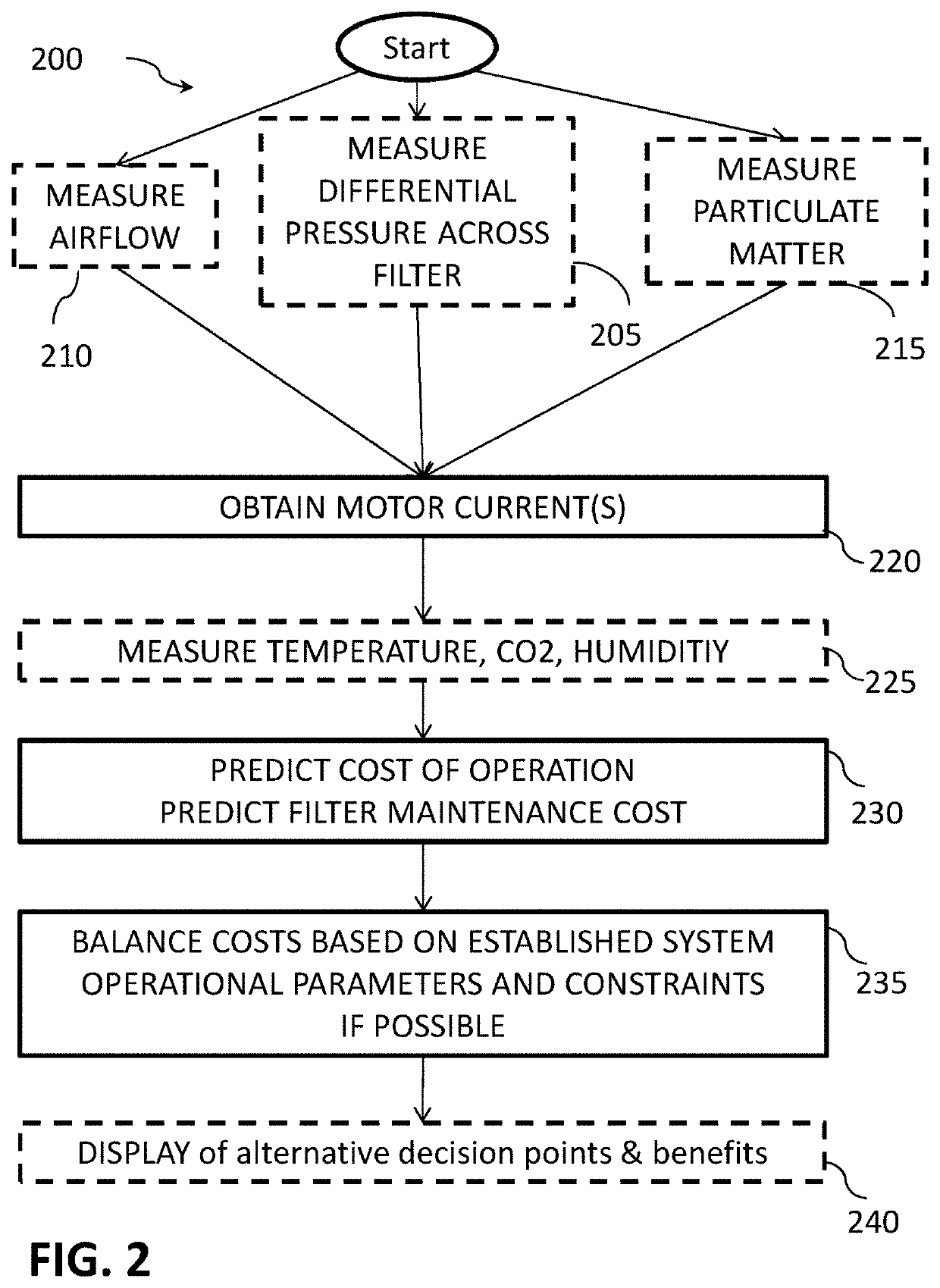
[0004]Described herein in an embodiment is a method for improving the efficiency and / or useful lifetime of an air circulation system in the air handling unit (AHU) a building having blower motor and a contaminant filter. The method includes ascertaining at least one of a differential pressure across the contaminant filter, a particulate matter concentration, and an airflow through the filter, and obtaining a current and / or voltage associated with the operation of the blower motor to produce the airflow. The method also includes predicting a cost of operation of the circulation system with respect to clean air delivery amount or rate over an operational duration based on at least an electrical current associated with the operation of the blower motor, predicting a cost of maintenance of the circulation system over the operational duration based on at least one of the differential pressure across the filter and the particulate matter concentration and airflow, balancing the cost of operation of the circulation system versus the cost of maintenance of the circulation system over the selected operational duration to recommend a filter maintenance schedule suiting operation objectives and constraints set by operators.
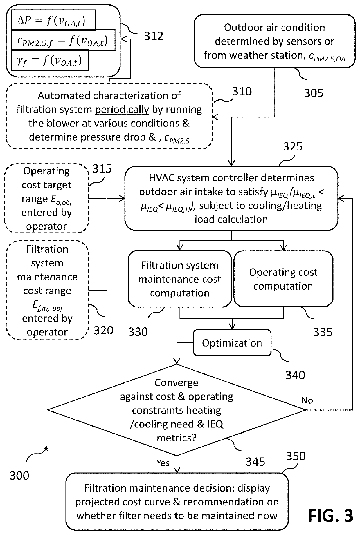
[0005]Also described herein in an embodiment is a method for improving the effectiveness of a building air circulation system having motorized blower and a contamination filter. The method including predicting a cost of operation of the system over an operational duration based on at least electricity consumption of the motor, and an operational cost to operate the filter, predicting a cost of maintenance of the system over the operational duration based on at least one of, a condition of the filter, a cost of a filter, a cost of labor to clean or replace the filter, and an effectiveness of the filter over the operational duration, and balancing the cost of operation of the circulation system versus the cost of maintenance of the circulation system over the duration to recommend at least one of a filter use / bypass schedule, a filter maintenance schedule, and a fresh air input schedule satisfying an operation objective and an operational constraint.
[0018]In addition to one or more of the features described above, or as an alternative, further embodiments may include that the predicting a cost of maintenance of the circulation system includes at least one of a cost of replacement filters, a cost of labor to replace filters, effectiveness of the filter over the operational duration.
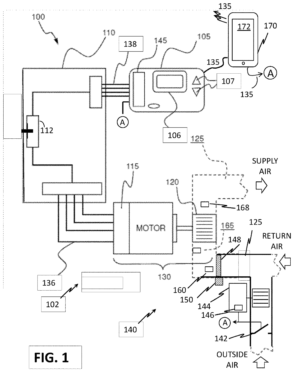
[0022]Also disclosed herein in an embodiment is a system for enhancing the operation and improving the effectiveness of an air circulation system in a building with in a heating, ventilation, and cooling (HVAC) system in a heating, ventilation, and cooling (HVAC) system. The system includes an air handler including an indoor blower and a motor operably coupled to a duct network, the blower configured to impart airflow to the air in the duct network, a contamination filter operably coupled to the duct network configured to remove contamination from air in the duct network, and at least one of a differential pressure sensor configured to measure a differential pressure across the contamination filter, a particulate concentration sensor configured to determine the presence of particulates in the air in the duct network after the contamination filter, an airflow sensor configured to measure airflow in the duct network. The system also includes an air handler controller in operable communication with at least the motor, the air handler controller configured to provide control commands to operate the motor and a controller in operable communication with the air handler controller and at least one of the differential pressure sensor, the particulate concentration sensor, and an airflow sensor, the controller configured to execute a method for enhancing the operation and improving the efficiency of an air circulation system in a building. The method including predicting a cost of operation of the circulation system over an operational duration based on at least an electricity consumption associated with operation of the blower motor and an operational cost to operate the contamination filter, predicting a cost of maintenance of the circulation system over the operational duration based on at least one of, an operational condition of the contamination filter, a cost of a replacement contamination filter, a cost of labor to clean or replace the contamination filter, and an effectiveness of the contamination filter over the operational duration, and balancing the cost of operation of the circulation system versus the cost of maintenance of the circulation system over the selected operational duration to recommend at least one of a contamination filter use / bypass schedule, a contamination filter maintenance schedule, and a fresh air input schedule satisfying an operation objective and an operational constraint set by an operator.

Problems solved by technology

High capacity filtration devices such as mechanical filters, electronic filters, and adsorptive devices can be effective at removing many undesired pollutants, but also can cause a significant pressure drop across the filters particularly as they are used longer and fill with contaminants.
In order to compensate for the pressure loss, more fan energy must be utilized, thus significantly increasing the operating costs of the system.
Scheduled maintenance as opposed to filter condition based maintenance can lead to additional labor cost than what can be potentially optimized.

Method used


Image

  • Condition based energy smart air circulation system
  • Condition based energy smart air circulation system
  • Condition based energy smart air circulation system

Examples


Embodiment Construction

[0029]For the purposes of promoting an understanding of the principles of the present disclosure, reference will now be made to the embodiments illustrated in the drawings, and specific language will be used to describe the same. It will nevertheless be understood that no limitation of the scope of this disclosure is thereby intended. The following description is merely illustrative in nature and is not intended to limit the present disclosure, its application or uses. It should be understood that throughout the drawings, corresponding reference numerals indicate like or corresponding parts and features. As used herein, the term controller refers to processing circuitry that may include an application specific integrated circuit (ASIC), an electronic circuit, an electronic processor (shared, dedicated, or group) and memory that executes one or more software or firmware programs, a combinational logic circuit, and / or other suitable interfaces and components that provide the described...


PUM


Abstract

A method for improving the effectiveness of a building air circulation system having motorized blower and a contamination filter. The method including predicting a cost of operation of the system over an operational duration based on at least electricity consumption of the motor (115), and an operational cost to operate the filter (148), predicting a cost of maintenance of the system over the operational duration based on at least one of, a condition of the filter (148), a cost of a filter (148), a cost of labor to clean or replace the filter (148), and an effectiveness of the filter (148) over the operational duration, and balancing the cost of operation of the circulation system versus the cost of maintenance of the circulation system over the duration to recommend at least one of a filter use / bypass schedule, a filter maintenance schedule, and a fresh air input schedule satisfying an operation objective and an operational constraint.

Description

FIELD OF INVENTION[0001]Embodiments relate generally to air flow control in an HVAC system and, more particularly, to a system and method for improved air flow control algorithms in an air handling unit of a ducted HVAC system that provides more optimized air circulation and filtration system operation and maintenance over the operating range of the air handler in view of indoor air quality, particulate matter management, and operating cost.DESCRIPTION OF RELATED ART[0002]Modern structures, such as office buildings and residences, utilize heating, ventilation, and cooling (HVAC) systems having controllers that allow users to control the environmental conditions within these structures. These controllers have evolved over time from simple temperature based controllers to more advanced programmable controllers, which allow users to program a schedule of temperature set points in one or more environmental control zones for a fixed number of time periods as well as to control the humidi...

Claims


Application Information

Patent Timeline
Patent Type & Authority Patents(United States)
IPC IPC(8): F24F11/74F24F11/39F24F11/47F24F11/64F24F11/65F24F11/58G05B19/042F24F110/50F24F130/00F24F110/52F24F11/00
CPCF24F11/47F24F11/39F24F11/58F24F11/64F24F11/65F24F11/74G05B19/042F24F2011/0002F24F2110/50F24F2110/52F24F2130/00G05B2219/2614F24F2110/64F24F2110/40F24F11/46Y02B30/70F24F3/16F24F8/10
Inventor CHEN, LEIZHAO, JIANWEIWEN, SANMINGMCKINNEY, PETER JOHANNES
Owner CARRIER CORP
Why Eureka
Try Eureka