
Vehicle control apparatus

a technology of control apparatus and steering wheel, which is applied in the direction of mechanical apparatus, transportation and packaging, roads, etc., can solve the problems of risk of long time required for completion so as to reduce the slow progress of coasting shift-down action and reduce the speed of vehicle running speed. , the effect of reducing the synchronizing shock of step-variable transmission

Active Publication Date: 2022-03-15
TOYOTA JIDOSHA KK
View PDF12 Cites 2 Cited by
  • Summary
  • Abstract
  • Description
  • Claims
  • Application Information

AI Technical Summary

Benefits of technology

The present invention is aimed at providing a control system for a vehicle with a step-variable automatic transmission that can reduce the synchronizing shock experienced during a low-speed coasting shift-down action. The system should prevent the shift from progressing too slowly and ensure smooth shifting without causing any discomfort to the driver.

Problems solved by technology

Accordingly, if the input torque is increased by a predetermined constant amount irrespective of the rate of change of the vehicle running speed, to raise the input speed, it takes a relatively long time for the input speed to reach the synchronization value so that the time required for completion of the coasting shift-down action is relatively long, when the rate of change of the vehicle running speed is relatively high.
Namely, there is a risk of a slow progress of the coasting shift-down action when the rate of change of the vehicle running speed is relatively high.
When the rate of change of the vehicle running speed is relatively low, on the other hand, the input speed is excessively rapidly raised toward the synchronization value, so that there is a risk of increase of a synchronizing shock of the step-variable transmission.

Method used


Image

  • Vehicle control apparatus
  • Vehicle control apparatus
  • Vehicle control apparatus

Examples


Embodiment Construction

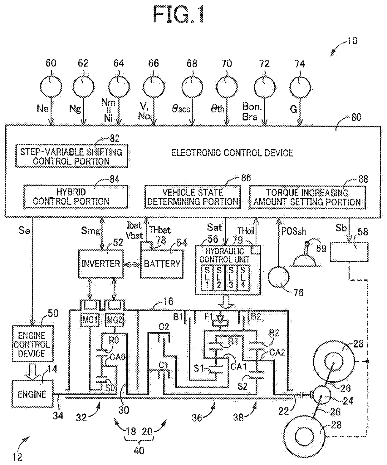
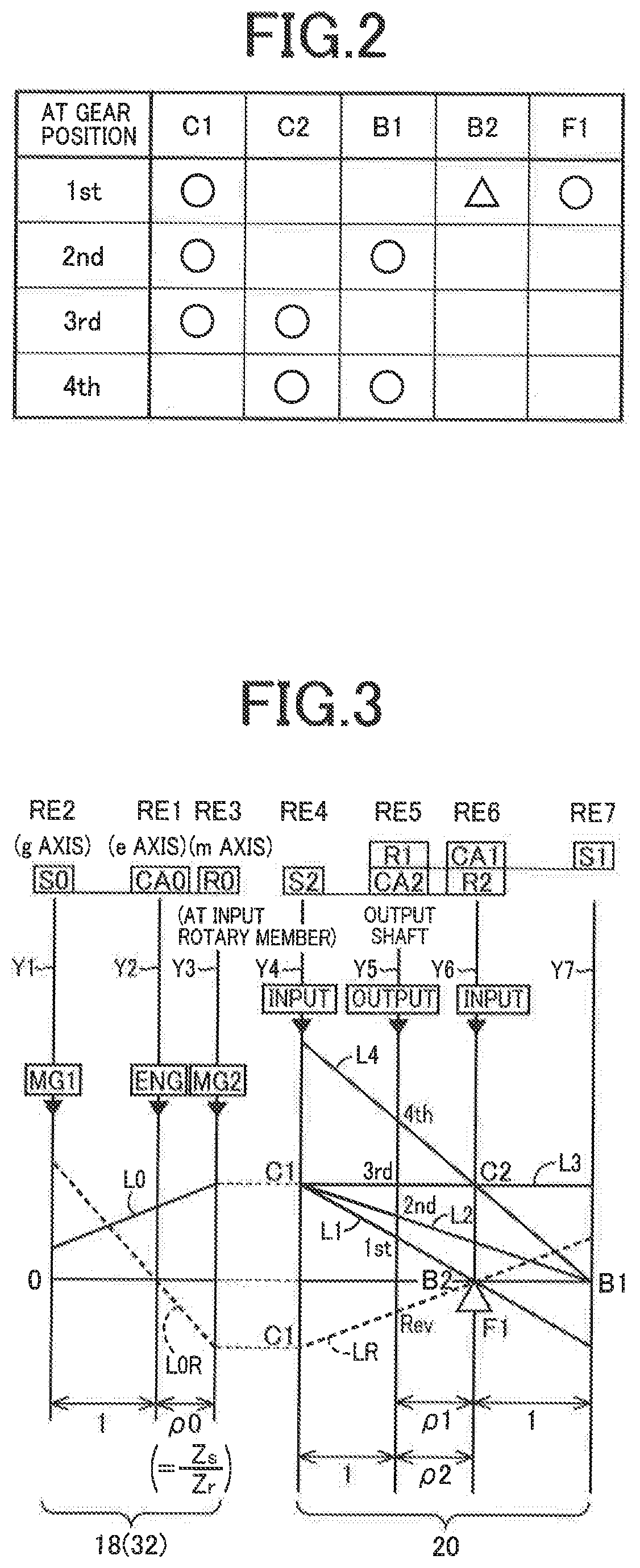
[0028]In the present specification, “a speed ratio” of each of the above-described step-variable transmission, and a transmission device consisting of the step-variable transmission and the above-described electrically controlled continuously-variable transmission mechanism which are disposed in series with each other is a ratio of a rotating speed of an input rotary member of the transmission or transmission device to a rotating speed of an output rotary member of the transmission or transmission device. A gear position or speed position of the transmission or transmission device which has a relatively low speed ratio is established or used for driving the vehicle at a relatively high running speed. On the other hand, a gear position or speed position of the transmission or transmission device which has a relatively high speed ratio is established or used for driving the vehicle at a relatively low running speed. For example, the gear position having the highest speed ratio is the ...


PUM


Abstract

A control apparatus for a vehicle having a step-variable transmission. The control apparatus includes: a shift control portion to temporarily increase an input torque of the step-variable transmission beyond a required value, the shift control portion commanding an engaging-side coupling device which is the coupling device placed in a released state, to be brought into an engaged state, when the input speed has been raised to a predetermined value; and a torque increasing amount setting portion to set an amount of increase of the input torque of the step-variable transmission beyond the required value, such that the amount of increase is smaller when a rate of change of a running speed of the vehicle is relatively low than when the rate of change is relatively high, the rate of change of the running speed having a negative value in a decelerating state of the vehicle.

Description

[0001]This application claims priority from Japanese Patent Application No. 2018-160784 filed on Aug. 29, 2018, the disclosure of which is incorporated herein by reference in its entirety.FIELD OF THE INVENTION[0002]The present invention relates to a control apparatus for a vehicle provided with a drive power source, drive wheels, and a step-variable transmission which constitutes a part of a power transmitting path between the drive power source and the drive wheels.BACKGROUND OF THE INVENTION[0003]There is well known a control apparatus for a vehicle provided with an engine, drive wheels, and a step-variable transmission which constitutes a part of a power transmitting path between the engine and the drive wheels and which has a plurality of coupling devices which are selectively engaged to establish a selected one of a plurality of gear or speed positions. For example, JP2009-166643A discloses a control apparatus for controlling this type of vehicular drive system. The control ap...

Claims


Application Information

Patent Timeline
Patent Type & Authority Patents(United States)
IPC IPC(8): B60W50/12B60W10/11B60W30/18F16H59/14F16H59/36F16H61/682
CPCB60W50/12B60W10/11B60W30/18F16H59/14F16H59/36F16H61/682B60W30/19B60W20/30B60W10/06B60W2520/10B60W2540/10B60W20/00B60W20/17B60W10/08B60K6/445B60W30/18072B60W2510/0657B60W2510/0638B60W2510/081B60W2510/083B60W2540/12B60W2540/16F16H61/0403Y02T10/62Y02T10/60F16H61/686F16H63/50F16H2059/405
Inventor SASADE, SHINICHIKUMAZAKI, KENTAGOTO, JUNSUGIYAMA, KOJIKIMURA, TAKAHIRO
Owner TOYOTA JIDOSHA KK
Learn More