Mounting structure and cooling fan

a technology of mounting structure and cooling fan, which is applied in the direction of machines/engines, mechanical equipment, liquid fuel engines, etc., can solve the problems of deterioration in vibration suppression, high cost, and inability to obtain vibration resistance effect easily, so as to achieve the effect of vibration resistance

Active Publication Date: 2022-03-15
FANUC LTD
View PDF35 Cites 0 Cited by
  • Summary
  • Abstract
  • Description
  • Claims
  • Application Information

AI Technical Summary

Benefits of technology

[0007]To solve this problem, a method of improving the vibration resistance of the cooling fan is brought out by increasing the rigidity of the cooling fan itself and the mounting rigidity of the cooling fan on the electric motor. In this case, it is possible to increase the rigidity of components of the cooling fan by using a high-strength material, increasing its dimensions or adding a reinforcing member. However, these methods result in a high cost, an increase in the dimensions of the cooling fan and an increase in weight. As a result, it becomes unable to balance the electric motor with the cooling fan in dimension or weight.
[0008]Therefore, an object of the present invention is to provide a mounting structure capable of suppressing vibration transmitted from the outside in a simple configuration. Further, another object of the present invention is to provide a cooling fan using such a mounting structure.
[0012]According to the present invention, it is possible to suppress (absorb) vibration transmitted from the outside in a simple configuration.

Problems solved by technology

In the case where vibration transmitted to a cooling fan is suppressed by the use of a vibration-proof material as is done in the mounting structure disclosed in Japanese Laid-Open Patent Publication No. 2015-204641, there is a concern about deterioration in vibration suppression because of degradation of the vibration proofing material over time depending on the ambient environment.
Further, vibration-resistance effect cannot be obtained easily because the vibration-proof material is fastened by the screw-engaging bolts and the female screw portions.
However, these methods result in a high cost, an increase in the dimensions of the cooling fan and an increase in weight.
As a result, it becomes unable to balance the electric motor with the cooling fan in dimension or weight.

Method used


Image

  • Mounting structure and cooling fan
  • Mounting structure and cooling fan
  • Mounting structure and cooling fan

Examples


first embodiment

Modifications of First Embodiment

[0041]Next, modifications (first to seventh modifications) of the mounting structure 10A in the first embodiment will be described with reference to FIGS. 1B to 4B. Incidentally, in the first to seventh modifications, those identical with or similar to the components of the mounting structure 10A shown in FIG. 1A will be given the same reference numerals and will be omitted from being described in detail.

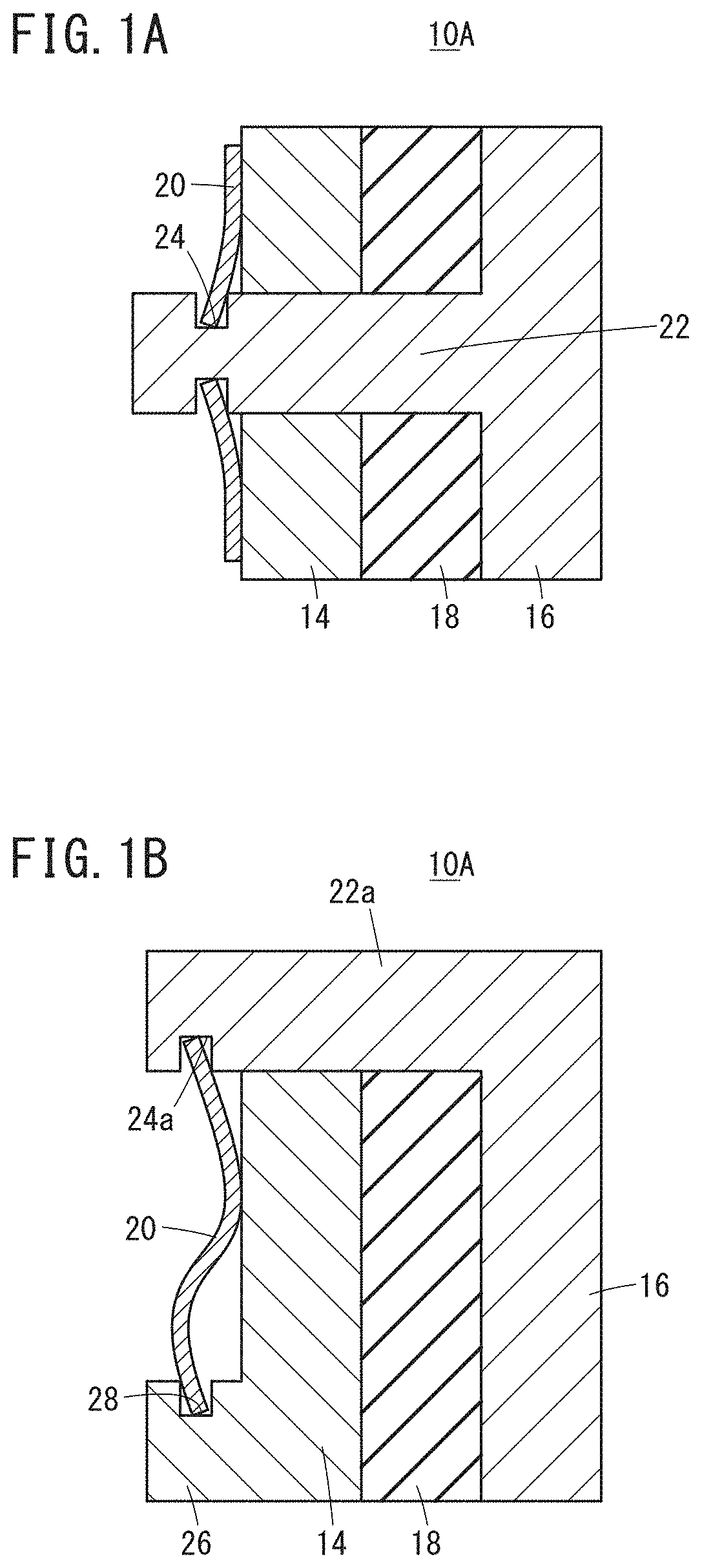
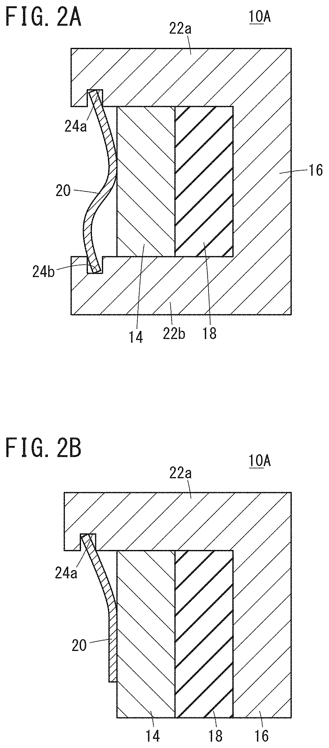
[0042]In the first modification shown in FIG. 1B, a support member 22a extends from one end portion of the second member 16 to a side of the first member 14 opposite to the joining member 18 along side surfaces of the joining member 18 and the first member 14. On the side of the first member 14 opposite to the joining member 18, there is provided a support portion 26 extending from the first member 14 in a direction away from the joining member 18. The support portion 26 is formed with a groove 28 facing a groove 24a of the support member 22a. In thi...

second embodiment

[0062]A mounting structure 10B in a second embodiment will be described with reference to FIGS. 5A and 5B.

[0063]In the mounting structure 10B, a portion of a first member 14 is inserted into a hole portion 54 formed in a second member 16, and a joining member 18 connects the inserted first member 14 to an inner wall of the hole portion 54. Furthermore, the inner wall of the hole portion 54 is provided with grooves 56 at places which are not provided with the joining member 18. Furthermore, portions of the first member 14 inserted into the hole portion 54 are formed with grooves 58 facing the grooves 56 of the second member 16 at places where the joining member 18 is not provided. Both ends of each metal portion 60 are fitted in the respective groove 56 and groove 58. Thus, the metal member 60 is fastened to the first member 14 and the second member 16 and restricts relative movement of the first member 14 to the second member 16 in the axial direction of the first member 14.

[0064]Du...

third embodiment

Modifications of Third Embodiment

[0076]With reference to FIGS. 8A to 9B, description will be given regarding modifications of the mounting structure 10C and the cooling fan 12 to which the mounting structure 10C in the third embodiment is applied.

[0077]In a modification shown in FIGS. 8A and 8B (hereafter, referred to as an eighth modification), a mounting structure 10C is applied to the cooling fan 12 in order to mount the propeller boss 68a of the propeller 68 and the plurality of blades 68b on each other. For example, the mounting structure 10A in the first embodiment shown in FIG. 1A is utilized as the mounting structure 10C.

[0078]In the eighth modification, an outer peripheral portion 72 of the propeller boss 68a is configured to extend downward toward the plurality of blades 68b, while inner side portions of the plurality of blades 68b are configured respectively as mounting portions 74 extending upward inside the outer peripheral portion 72 of the propeller boss 68a. The moun...


PUM


Abstract

A mounting structure for mounting a first member and a second member on each other forming a device such as a cooling fan or the like. The mounting structure is equipped with a rubber joining member provided between the first member and the second member, having a curing property and joining the first member and the second member, and a first metal member provided on the first member on a side opposite to the joining member and having an elastic force restricting the relative movement of the first member to the second member.

Description

CROSS-REFERENCE TO RELATED APPLICATION[0001]This application is based upon and claims the benefit of priority from Japanese Patent Application No. 2017-161067 filed on Aug. 24, 2017, the contents of which are incorporated herein by reference.BACKGROUND OF THE INVENTIONField of the Invention[0002]The present invention relates to a mounting structure for mounting a first member and a second member on each other and a cooling fan having the mounting structure.Description of the Related Art[0003]In various machines such as machine tools, industrial machinery and the like, an electric motor is mounted for rotating a rotational shaft such as a feed shaft, a main spindle or the like. A cooling fan is mounted on the electric motor and forcibly cools the electric motor for improving heat dissipation from the surface of the electric motor to improve the characteristic of a continuous rated torque or the like.[0004]However, there may be the case that large vibration is applied to the cooling f...

Claims


Application Information

Patent Timeline
Patent Type & Authority Patents(United States)
IPC IPC(8): F04D29/34F16F15/073H02K7/00F04D29/66F04D29/20F04D25/08F16F15/08F04D29/054H02K9/06F04D29/052F04D29/056
CPCF16F15/073F04D25/082F04D29/054F04D29/20F04D29/668F16F15/085H02K7/003H02K9/06F04D29/052F04D29/056F04D25/08F04D29/002F04D29/5806
Inventor LEE, SEUNGJUN
Owner FANUC LTD
Why Eureka
Try Eureka