Pneumatic tire

a technology of pneumatic tires and tyres, which is applied in the field of pneumatic tires, can solve the problems of increasing the modulus causing the separation between the earthing tread and the cap tread, and reducing the braking performance of the tire, so as to ensure the low rolling resistance of the tire, and improve the braking performance. the effect of ice performan

Active Publication Date: 2022-03-22
THE YOKOHAMA RUBBER CO LTD
View PDF28 Cites 0 Cited by
  • Summary
  • Abstract
  • Description
  • Claims
  • Application Information

AI Technical Summary

Benefits of technology

[0005]The present technology provides a pneumatic tire that can provided improved separation resistance performance while maintaining performance on ice.
[0007]In a pneumatic tire according to an embodiment of the technology, the modulus at 300% elongation of the cap tread ranging from 3.0 Mpa to 7.0 Mpa is advantageous in appropriately setting the modulus M_cap of the cap tread and thus improving the performance on ice (braking performance on ice) of the tire. Additionally, the earthing tread and the undertread having an integral structure made from the same rubber material is advantageous in effectively suppressing the separation at the boundary face between the earthing tread and thus the cap tread and improving the separation resistance performance of the tire.

Problems solved by technology

However, increasing the silica content of the cap tread increases the difference in modulus between the earthing tread and the cap tread.
This increases the difference in ground contact pressure between the earthing tread and the cap tread, causing separation at the boundary face between the earthing tread and the cap tread to readily occur.

Method used


Image

  • Pneumatic tire
  • Pneumatic tire
  • Pneumatic tire

Examples


modified examples

[0115]FIGS. 6 to 8 are explanatory diagrams illustrating modified examples of the block illustrated in FIG. 3. In these drawings, constituents that are the same as those illustrated in FIG. 3 have the same reference signs, and explanations thereof are omitted.

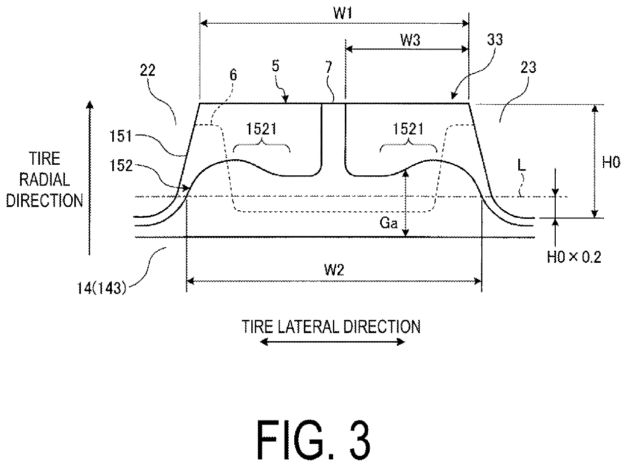
[0116]In the configuration of FIG. 3, the earthing tread 7 is disposed in the central portion of the block 5, and the undertread 152 includes the thickened portion 1521 in each of the regions to the left and right of the earthing tread 7.

[0117]However, no such limitation is intended, and the earthing tread 7 may be disposed closer to one of the edge portions of the block 5 (see FIGS. 6 and 7). Additionally, the undertread 152 may include the thickened portion 1521 in only one of the regions to the left and right of the earthing tread 7 (see FIGS. 6 and 7) or may not include the thickened portion 1521 (see FIG. 8).

[0118]For example, in the configurations of FIGS. 6 and 7, the earthing tread 7 is disposed closer to one of the edg...

examples

[0138]FIGS. 9A-9B include a table showing the results of performance tests of pneumatic tires according to embodiments of the technology. FIG. 10 is an explanatory diagram illustrating a test tire of the Conventional Example.

[0139]In the performance tests, a plurality of mutually differing pneumatic tires were evaluated for (1) braking performance on ice, (2) electrostatic suppression performance (electrical resistance value), and (3) separation resistance performance (see FIGS. 9A-9B). In the performance tests, pneumatic tires having a tire size of 195 / 65R15 91Q were mounted on rims having a rim size of 15×6J, inflated to an air pressure of 210 kPa, and loaded with the load specified by JATMA. The pneumatic tires were mounted on the test vehicle, a four wheel drive sedan with an engine displacement of 3.0 L.

[0140](1) In the evaluation relating to braking performance on ice, the test vehicle was driven on a predetermined icy road surface and the braking distance from a travel speed ...


PUM

PropertyMeasurementUnit
elongationaaaaaaaaaa
inclination angleaaaaaaaaaa
belt angleaaaaaaaaaa

Abstract

In a pneumatic tire, a modulus at 300% elongation of a cap tread ranges from 3.0 Mpa to 7.0 Mpa, and the modulus at 300% elongation of an undertread ranges from 10.0 Mpa to 20.0 Mpa. Additionally, an earthing tread is made from a rubber material with a volume resistivity of 1×10{circumflex over ( )}7 Ω·cm or less. The earthing tread is made from the same rubber material as the undertread and has an integral structure with the undertread.

Description

TECHNICAL FIELD[0001]The technology relates to a pneumatic tire and particularly relates to a pneumatic tire that can provide improved separation resistance performance while maintaining performance on ice.BACKGROUND ART[0002]Studless tires are required to have good performance on ice and performance on snow, as well as good wet performance and rolling resistance. Accordingly, in recent years, a tread structure in which the rubber compound of the cap tread has an increased silica content has been employed.[0003]However, because silica is a good insulator, the electrical resistance value of the cap tread increases when the silica content of the cap tread increases. Accordingly, the tire-to-road surface electrical discharge properties decrease and the electrostatic suppression performance of the tire decreases. Because of this, recent studless tires have employed an electrostatic suppressing structure including an earthing tread. The technologies described in Japan Patent Nos. 3964511...

Claims


Application Information

Patent Timeline
Patent Type & Authority Patents(United States)
IPC IPC(8): B60C19/08B60C11/12B60C11/00B60C11/03B60C11/11
CPCB60C19/08B60C11/00B60C11/005B60C11/0327B60C11/11B60C11/12B60C11/1236B60C11/1259B60C2011/0025B60C2011/0353B60C2011/1213B60C11/0041B60C19/082B60C11/0306B60C1/0016Y02T10/86
Inventor KISHIZOE, ISAMU
Owner THE YOKOHAMA RUBBER CO LTD
Why Eureka
Try Eureka