Charging system

a charging system and charging technology, applied in the direction of battery/fuel cell control arrangement, transportation and packaging, instruments, etc., can solve the problems of insufficient power supply facilities, other users cannot use power supply facilities, etc., to increase the improve user convenience, and increase the effect of user turnover rate of power supply facilities

Active Publication Date: 2022-03-22
TOYOTA JIDOSHA KK +1
View PDF23 Cites 2 Cited by
  • Summary
  • Abstract
  • Description
  • Claims
  • Application Information

AI Technical Summary

Benefits of technology

[0005]When the user stays in the installation for a long time, the user is more likely to utilize merchandise items and services offered by the installation. On the other hand, however, while the user is using the power supply facility, other users cannot use the power supply facility. When power supply facilities in the parking area have been used for a long time, the number of users per unit time for each power supply facility (hereinafter, also referred to as “user turnover rate”) is decreased, with the result that the number of power supply facilities in a state (hereinafter, also referred to as “vacant state”) in which the power supply facilities are used by no one may become insufficient.
[0023]As described above, by issuing the coupon not only after the first notification but also after the second notification, the user can be motivated to stop using the power supply facility immediately after the second notification. Further, in the above-described charging system, the usage value of the coupon issued after the first notification is higher than the usage value of the coupon issued after the second notification. The timing of the second notification tends to be set to a timing after the first notification in consideration of the user's convenience. The first notification is highly likely to be performed at a timing earlier than the timing of the second notification. By increasing the usage value of the coupon issued after the first notification as described above, the user is urged to return to the location of the vehicle immediately (that is, stop using the power supply facility) in response to the first notification. By giving such an incentive to the user to stop using the power supply facility immediately, the user turnover rate of the power supply facility can be increased.

Problems solved by technology

On the other hand, however, while the user is using the power supply facility, other users cannot use the power supply facility.
When power supply facilities in the parking area have been used for a long time, the number of users per unit time for each power supply facility (hereinafter, also referred to as “user turnover rate”) is decreased, with the result that the number of power supply facilities in a state (hereinafter, also referred to as “vacant state”) in which the power supply facilities are used by no one may become insufficient.
However, even when such a notification is provided to the user, the user may ignore the notification or may not notice the notification.
It is also considered to provide such a notification to the user frequently; however, the user's convenience may be impeded by frequently providing such a notification.
Also, a large number of vehicles waiting for a currently used power supply facility to be available means that a demand for power supply facilities is high.

Method used


Image

  • Charging system
  • Charging system
  • Charging system

Examples


Embodiment Construction

[0034]The following describes embodiments of the present disclosure with reference to figures in detail. The same or corresponding portions in the figures are given the same reference characters and are not described repeatedly.

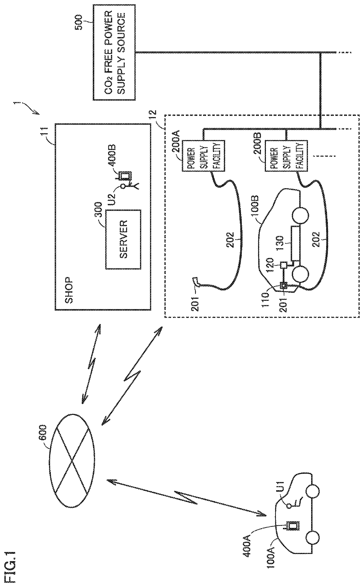
[0035]FIG. 1 schematically shows an entire configuration of a charging system according to the present embodiment. This charging system includes an installation 1, vehicles 100A, 100B, user terminals 400A, 400B, a CO2 free power supply source 500, and a communication network 600. Installation 1 includes power supply facilities 200A, 200B. It should be noted that the basic configuration of vehicle 100A is the same as the basic configuration of vehicle 100B. The basic configuration of power supply facility 200A is the same as the basic configuration of power supply facility 200B. The basic configuration of user terminal 400A is the same as the basic configuration of user terminal 400B. Therefore, in the description below, vehicle 100A and vehicle 100B may be de...


PUM


Abstract

A charging system includes a vehicle, a power supply facility, a mobile terminal, and a server. The power supply facility performs external charging by supplying power to the vehicle. The mobile terminal receives a user input from a user of the vehicle and provides a notification to the user. The server communicates with the mobile terminal. The mobile terminal sets a first notification condition in the server in response to the user input. A second notification condition is set in the server in advance. The server determines whether or not each of the first notification condition and the second notification condition is satisfied during the external charging. When the first notification condition is satisfied, the server provides a first notification to the user through the mobile terminal. When the second notification condition is satisfied, the server provides a second notification to the user through the mobile terminal.

Description

[0001]This nonprovisional application is based on Japanese Patent Application No. 2018-240109 filed on Dec. 21, 2018 with the Japan Patent Office, the entire contents of which are hereby incorporated by reference.BACKGROUNDField[0002]The present disclosure relates to a charging system, particularly, a charging system including a power supply facility that supplies power to a vehicle.Description of the Background Art[0003]Japanese Patent Laying-Open No. 2012-244785 discloses a charging system including notification means for transmitting an e-mail to a mobile terminal of a user who uses an installation having a parking area. When a certain period of time has passed since a charging start time with an onboard battery of an electric vehicle being charged using a power supply facility provided in the parking area, this notification means transmits the e-mail to the mobile terminal of the user.SUMMARY[0004]In the charging system described in Japanese Patent Laying-Open No. 2012-244785, w...

Claims


Application Information

Patent Timeline
Patent Type & Authority Patents(United States)
IPC IPC(8): B60L53/30G06Q30/04H04W68/00B60L53/62H02J7/00B60L58/13
CPCB60L53/305B60L53/62B60L58/13G06Q30/04H02J7/0048H04W68/005B60L53/68G06Q50/06G06Q50/10Y02T90/16Y02T10/70Y02T10/7072Y02T90/14Y02T90/12B60L2250/16B60L2240/80
Inventor MURAMATSU, MAKITOSHIBANO, TAKUMITANAKA, MASASHIOCHIAI, TAKASHIFUKUI, TAKEHARUTAKAMURA, YOSHIHIROYOKOGAWA, TAKAHIROOHGASHIRA, MASASHI
Owner TOYOTA JIDOSHA KK
Why Eureka
Try Eureka