Water-source heat pump water-saving high-efficiency recharge system

A technology of water source heat pumps and water source heat pump units, applied in heat pumps, heating devices, geothermal energy power generation, etc., can solve problems such as increasing water intake, increasing initial investment costs, increasing equipment wear, etc., to improve operating efficiency, control and adjust Convenience and the effect of preventing well accidents

Active Publication Date: 2016-02-03
郭兴海
View PDF8 Cites 0 Cited by
  • Summary
  • Abstract
  • Description
  • Claims
  • Application Information

AI Technical Summary

Problems solved by technology

[0002] The most common problem with current water source heat pumps is that the pumped groundwater is difficult to fully recharge after being used by the heat pump, and the phenomenon of stolen drainage is very serious, wasting precious groundwater resources
The reason is that recharge wells often occur. This is because the directly extracted raw water (especially surface water) generally contains a large amount of impurities such as fine sand. If it is directly used for recharge, it is easy to plug the well. In addition, it contains If the water with a lot of impurities is directly supplied to the water source heat pump unit, it will not only easily cause pipeline blockage, but also increase the wear and tear of the equipment, which will seriously affect the working efficiency and service life of the equipment, and bring great inconvenience to maintenance. Directly recharge after utilization, the energy contained in it is not effectively utilized, resulting in low energy utilization efficiency, while increasing the amount of water harvested, and at the same time increasing the number of pumping wells and corresponding return wells, which increases the cost of initial investment, which is not conducive to water source heat pumps. Promotion and application of clean and renewable energy

Method used


Image

  • Water-source heat pump water-saving high-efficiency recharge system
  • Water-source heat pump water-saving high-efficiency recharge system

Examples


Embodiment Construction

[0014] Below in conjunction with accompanying drawing, the specific embodiment of the present utility model will be further described.

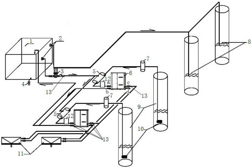
[0015] The utility model is realized in this way, which includes: a water separation treatment device 1, a filter 2, a water source heat pump unit 6, a swirl sand remover 7, a return well 8, a water well 9, a submersible pump 10, and a fan coil unit 11 And throttle valve 13, its structure is: it also includes heat pump water supply pump 3 and water mixer 5, one end of said heat pump water supply pump 3 is connected to water mixer 5 through pipeline, and the other end is connected with water separation treatment through pipeline The filter 2 on the upper part of the device 1 is connected, and the water separation treatment device 1 and the return well 8 are connected through pipelines; the water mixer 5, the cyclone sand remover 7 and the submersible pump 10 located in the pumping well 9 are sequentially connected in series. On the same pipeli...


PUM


Abstract

The invention discloses a water-saving efficient injection system for water-source heat pumps. The water-saving efficient injection system is structurally characterized in that one end of a water supply pump of the heat pumps is connected with a water mixer by a pipeline, the other end of the water supply pump is connected with filters by pipelines, the filters are positioned on the upper portion of a water distributing and treating device, and the water distributing and treating device is connected with return water wells by pipelines; the water mixer, a cyclone sand remover and submersible pumps are sequentially serially connected onto the same pipeline, the submersible pumps are positioned in pumping wells, the water mixer is connected with a port a of a water-source heat pump unit, a pipeline is connected between a port b of the water-source heat pump unit and the top of the water distributing and treating device, the port b and the port a of the water-source heat pump unit are positioned on the same side, a port c and a port d of the water-source heat pump unit are connected with a fan coil by pipelines, and the port c and the port d of the water-source heat pump unit are opposite to the port a. The water-saving efficient injection system has the advantages that water is led to the water distributing and treating device via the corresponding pipeline after being utilized by the water-source heat pumps, and can be injected to the return water wells and supplemented to the water-source heat pump unit via the water distributing and treating device; the water-saving efficient injection system is high in injection efficiency, the utilization rate of energy contained in the water can be increased, water resource exploitation can be reduced, and the initial investment and the operating cost can be decreased.

Description

technical field [0001] The utility model relates to a water-saving and high-efficiency recharge system for a water source heat pump. Background technique [0002] The most common problem with current water source heat pumps is that the extracted groundwater is difficult to fully recharge after being used by the heat pump, and the phenomenon of stolen drainage is very serious, wasting precious groundwater resources. The reason is that recharge wells often occur. This is because the directly extracted raw water (especially surface water) generally contains a large amount of impurities such as fine sand. If it is directly used for recharge, it is easy to plug the well. In addition, it contains If the water with a lot of impurities is directly supplied to the water source heat pump unit, it will not only easily cause pipeline blockage, but also increase the wear and tear of the equipment, which will seriously affect the working efficiency and service life of the equipment, and b...

Claims


Application Information

Patent Timeline
Patent Type & Authority Patents(China)
IPC IPC(8): F25B30/06F24J3/08
CPCY02E10/10
Inventor 郭兴海
Owner 郭兴海
Why Eureka
Try Eureka