Fuel cell system

a fuel cell and system technology, applied in the field of fuel cell systems, can solve the problems of reduced cell capacity, performance degradation, and secondary battery temperature not being increased at a favorable speed, and achieve the effect of discharging power and not increasing the temperature of secondary batteries

Inactive Publication Date: 2017-12-14
TOYOTA JIDOSHA KK
View PDF0 Cites 1 Cited by
  • Summary
  • Abstract
  • Description
  • Claims
  • Application Information

AI Technical Summary

Benefits of technology

[0006]Because an amount of the power that can be stored in the capacitor is small, a heating value that is acquired by the charging and the discharging of the power between the secondary battery and

Problems solved by technology

As a result, performance degradation such as decreased cell capacity occurs.
Thus, the temperature of the secondary battery ma

Method used


Image

  • Fuel cell system
  • Fuel cell system
  • Fuel cell system

Examples


Embodiment Construction

[0022]A detailed description will hereinafter be made on embodiments with reference to the drawings. Note that the scope of the disclosure is not limited thereto.

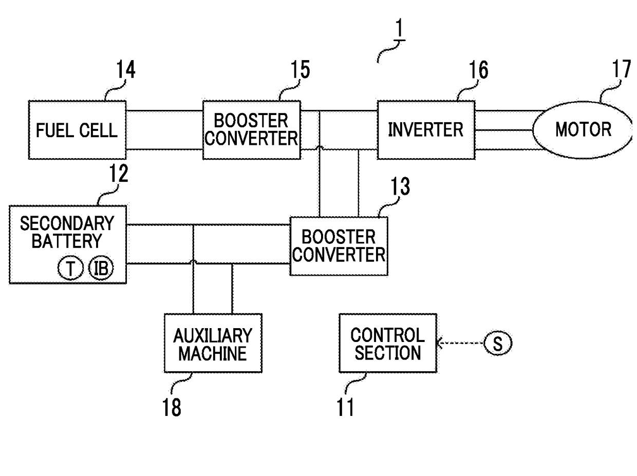
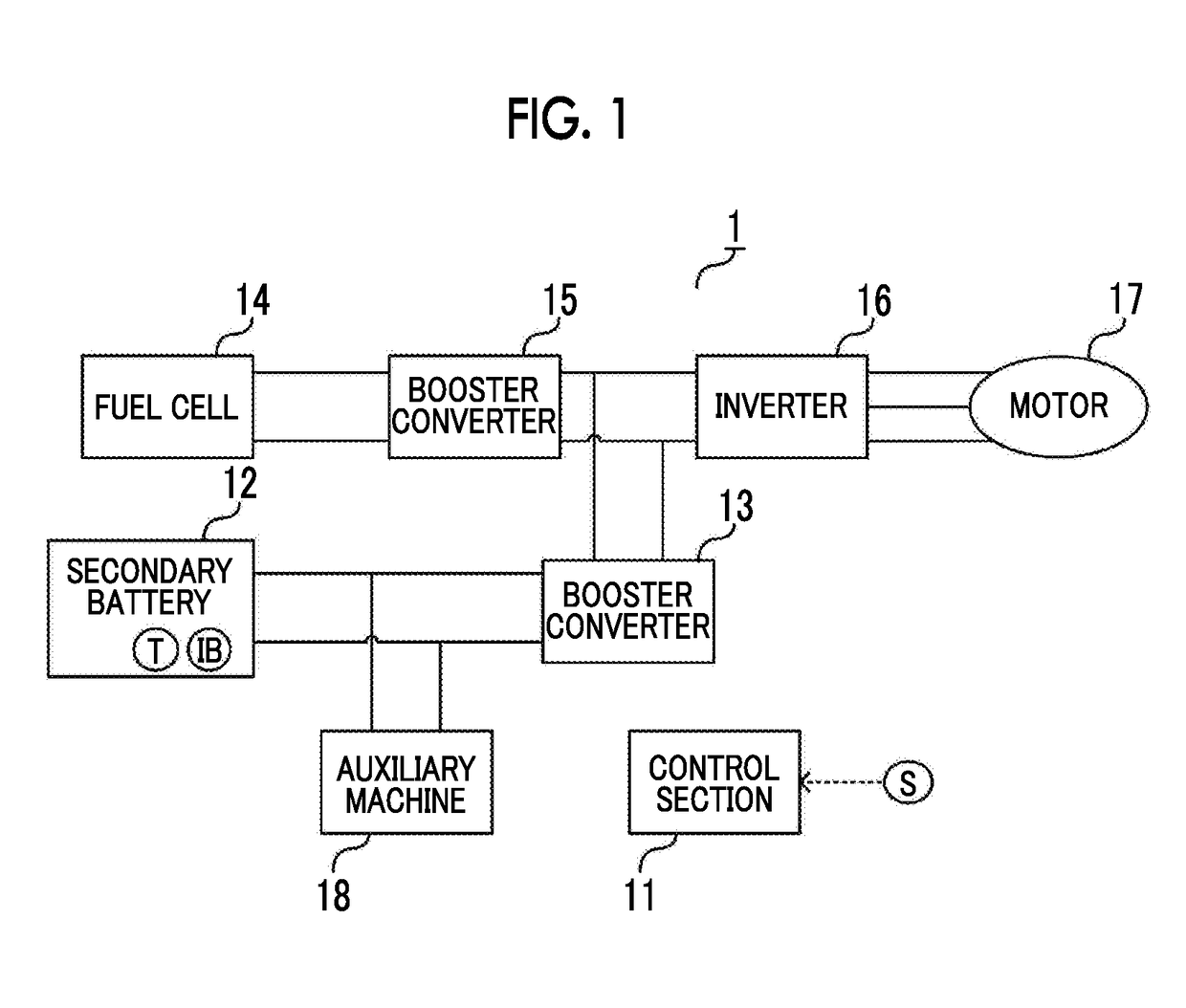
[0023][Configuration of Fuel Cell System] Referring to FIG. 1, a description will be made on an example of a schematic configuration of a fuel cell system in the embodiment. A fuel cell system 1 includes, as main components, a control section 11, a secondary battery 12, a booster converter 13, a fuel cell 14, a booster converter 15, an inverter 16, a motor 17, an auxiliary machine 18, and a speed sensor S.

[0024]The fuel cell system 1 is a system that can be mounted on a vehicle (mobile object) such as a fuel cell vehicle (FCV). Note that FIG. 1 merely shows the main components of the fuel cell system 1, and thus the fuel cell system 1 can include other components that are provided in a well-known fuel cell system mounted on the mobile object.

[0025]The secondary battery 12 is a power storage section that can be charged and d...


PUM


Abstract

A fuel cell system includes a drive motor, a fuel cell, an auxiliary machine, a secondary battery, a temperature sensor, a current sensor, and a control section. The control section controls the secondary battery for discharging by driving the drive motor or the auxiliary machine and for charging through power generation by the fuel cell or regeneration by the drive motor when a temperature measured by the temperature sensor is lower than a specified value.

Description

INCORPORATION BY REFERENCE[0001]The disclosure of Japanese Patent Application No. 2016-114542 filed on Jun. 8, 2016 including the specification, drawings and abstract is incorporated herein by reference in its entirety.BACKGROUND1. Technical Field[0002]The disclosure relates to a fuel cell system.2. Description of Related Art[0003]In recent years, attention has been paid to a fuel cell vehicle on which a fuel cell system using a fuel cell and a secondary cell (battery) as power supplies is mounted. Power supplied from the fuel cell system is supplied to electrical loads including a traveling motor and auxiliary machines (for example, a radiator fan, a coolant pump, a lamp, and the like).[0004]When a temperature of the secondary battery is decreased, charging and discharging characteristics of the secondary battery are degraded. For example, when a low-temperature lithium-ion cell is charged, lithium (Li) is precipitated on a negative electrode. As a result, performance degradation s...

Claims


Application Information

Patent Timeline
IPC IPC(8): B60L11/18G01P3/00H01M10/48G01R31/36H02J7/00H01M10/44H01M10/0525B60L7/10H01M16/00
CPCB60L11/1872B60L2210/14H01M16/006H01M10/443H01M10/0525B60L11/1887B60L7/10H02J7/0068G01P3/00G01R31/3613H01M2250/20H01M2250/402H01M2220/20B60L2240/12H01M10/486H01M10/613H01M10/625H01M10/633H01M10/667B60L58/32B60L7/16H01M10/48B60L7/14B60L2240/545H01M10/052H02J7/1438B60L58/40B60L58/25Y02E60/10Y02T10/70Y02T90/40Y02E60/50G01R31/3832B60L3/0046G01R31/44
Inventor FUKAMI, TATSUYAASO, SHINJIWATANABE, TAKAO
Owner TOYOTA JIDOSHA KK
Why Eureka
Try Eureka