Spark plug production method

Active Publication Date: 2019-12-26
NGK SPARK PLUG CO LTD
View PDF0 Cites 1 Cited by
  • Summary
  • Abstract
  • Description
  • Claims
  • Application Information

AI Technical Summary

Benefits of technology

[0026]In this configuration, the repetition period at which the pulsed energy beam is applied in the second sub-period of time can be shortened without increasing the average of the output energy per unit time. Therefore, an increase in time between energy beam pulses during which the energy beam is

Problems solved by technology

When the power of the laser beam is reduced, proper welding may not be possible.
For example, in some cases, the laser beam becomes unstable, and the irradiation w

Method used


Image

  • Spark plug production method
  • Spark plug production method
  • Spark plug production method

Examples


first embodiment

A. First Embodiment

[0034]A-1. Structure of Spark Plug 100:

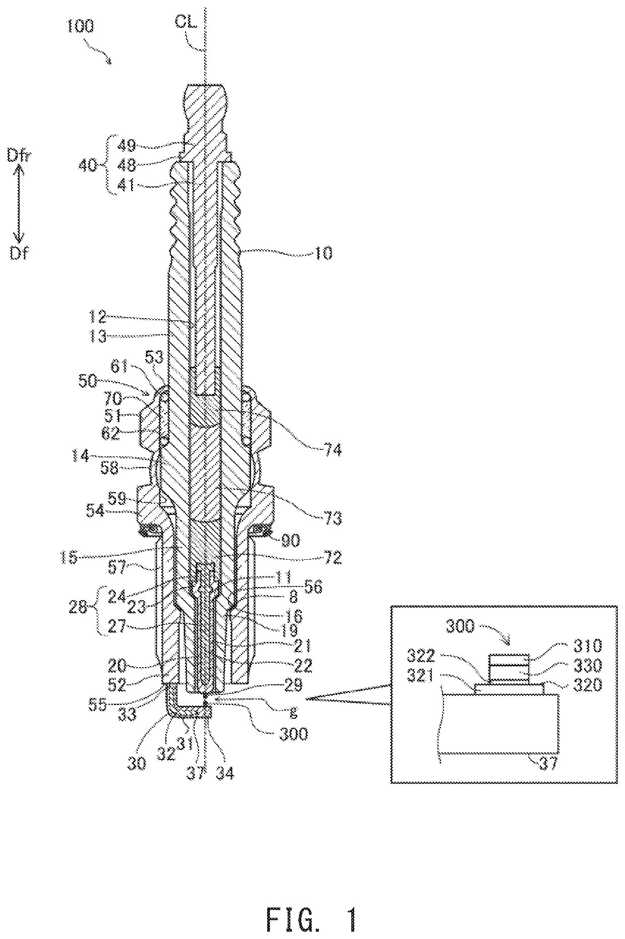
[0035]FIG. 1 is a cross-sectional view of a spark plug 100 of an embodiment which includes an electrode with a tip. This figure shows a center axis CL (which may be referred to also as an “axial line CL”) of the spark plug 100 and a flat cross section of the spark plug 100 that contains the center axis CL. Hereinafter, a direction parallel to the center axis CL is referred to as the “direction of the axial line CL” or simply as the “axial direction” or the “front-back direction.” A direction perpendicular to the axial line CL is referred to also as a “radial direction.” A circumferential direction of a circle centered at the axial line CL is referred to simply as a “circumferential direction.” A direction parallel to the center axis CL and toward the lower side in FIG. 1 is referred to a forward end direction Df or a forward direction Df, and a direction toward the upper side is referred to as a rearward end direction Dfr or ...

second embodiment

B. Second Embodiment

[0086]FIG. 6 is a pair of illustrations used for describing another embodiment of the ground electrode. A forward end portion of a ground electrode 30b is shown in FIG. 6. The ground electrode 30b can be used instead of the ground electrode 30 of the spark plug 100 in FIG. 1. A center axis CL and directions Df and Dfr in the figures represent the center axis CL and directions Df and Dfr, respectively, as viewed from the distal end portion 34 of the main body 37 of the ground electrode 30b in the completed spark plug 100. Their positional relation will be described using the center axis CL and the directions Df and Dfr. FIG. 6(A) shows their appearance when they are viewed in a direction parallel to the center axis CL (specifically in the forward direction DO, and FIG. 6(B) shows their appearance when they are viewed in a direction perpendicular to the center axis CL. In the present embodiment, instead of the tip portion 300 (FIG. 1), a tip 310b is welded to the r...


PUM

PropertyMeasurementUnit
Timeaaaaaaaaaa
Energyaaaaaaaaaa

Abstract

A tip is welded appropriately using an energy beam. The tip is welded to a base portion by irradiating the interface between the base portion and the tip with the energy beam. The welding the tip to the base portion includes: applying the energy beam continuously, while moving the irradiation position of the energy beam, in a first period of time; and applying the energy beam a plurality of times according to a pulsed output pattern, while moving the irradiation position of the energy beam, in a second period of time subsequent to the first period of time.

Description

FIELD OF THE INVENTION[0001]The present description relates to a spark plug including an electrode having a base portion and a tip fixed to the base portion.BACKGROUND OF THE INVENTION[0002]In some cases, to improve the durability of an electrode (e.g., a center electrode or a ground electrode) of a spark plug, a highly durable tip (for example, a tip containing a noble metal) is fixed to the electrode. One technique proposed to fix a ground electrode tip is to weld the tip to a ground electrode by irradiating the interface between the ground electrode and the ground electrode tip with, for example, a laser beam while moving the laser beam. In another proposed technique, the power of the laser beam is gradually reduced in consideration of the fact that heat imparted by the laser beam transfers through a molten portion to cause the temperature of a portion unirradiated with the laser beam to increase. For a prior art example, see Japanese Patent Application Laid-Open (kokai) No. 2012...

Claims


Application Information

Patent Timeline
IPC IPC(8): H01T13/20H01T21/02B23K26/0622B23K26/08B23K26/28
CPCB23K26/28B23K26/0876H01T21/02H01T13/39H01T13/20B23K26/0622B23K2101/36B23K26/0626B23K26/0823H01T13/32
Inventor TENKUMO, YUSUKEIMAI, SUSUMU
Owner NGK SPARK PLUG CO LTD
Why Eureka
Try Eureka