In this position, when the chain is fully settled in the larger chain-ring (as well as when it is fully settled on the smaller chain-ring) the main limitations of disclosure EP-0945335-A1 show up; due to the large reductions on the teeth profile, it is possible that power transmission is not appropriate at those points and even chain slippage out of the chain-ring can occur due to external vibrations.
Therefore, it is preferable to maintain a more complete teeth profile as it is shown in disclosure U.S. Pat. No. 8,092,329-B2, even if this implies more contact and friction during the shifting process, thus becoming essential the use of a derailleur or chain-pushing element that can exert a high force for the shifting to take place, resulting in a more abrupt and less reliable shifting process.
Shifting starts with the derailleur pressing on the side of the chain against the teeth of the smaller chain-ring, so that the chain eventually rises above these teeth and laterally surpasses them, thus disengaging from the larger chain-ring and breaking proper power transmission.
Also, it shows that the contact with the teeth of the smaller chain-ring is not performed optimally, synchronization is not good, and so it requires a longer stage III for the chain to settle on the smaller chain-ring as compared to a shifting towards a larger chain-ring.
In general, in is not possible to synchronize both processes (chain “rise” and “descent”), and usually the chain “rise” process is prioritized.
The disadvantage of these larger teeth is that, once again, they require the use of a derailleur or a chain-pushing element, which implies a more abrupt and less reliable shifting process.
Due to the chain's lack of stability during power transmission and not being able to shift chain-rings “at will” (since it is necessary to move the rear derailleur to certain sprockets in order to trigger the shifting), the disclosure described in EP-0945335-A1 did not get any market acceptance.
During this process high friction occurs between the chain and the chain-rings which implies a waste of energy, accelerates wear of transmission elements and may even lead to earlier transmission breakage.
During the shifting process, power transmission is also highly affected due to the large time intervals in which the chain is not properly supported by the force transmitting tooth, which not only enhances wear and increases the possibilities of breakage of these elements, but can also cause loss of contact between chain and tooth.
Because of this the chain can jump, thus invalidating the shifting or even generating the chain to come off any chain-ring, which ends up preventing power transmission.
However, if the shifting is executed at another point (out of these “paths”) or the chain is held with friction until reaching these optimal shift points, or shifting starts in a non-optimal point, there is a high risk of ending up in a failed shifting operation.
This problem with chain-ring shifting is even more significant with non-round chain-rings (e.g. oval-shaped chain-rings), where the distance between the chain-ring teeth and the pushing-element (derailleur) is variable so the efficiency of the actuator decreases.
The limitation of these systems is that the transmission ratio shifting occurs during the pedalling cycle and it is not controllable by the user.
Therefore, in order to have different gear ratios in different pedalling cycles, it is necessary to have additional chain-rings (round or not), and perform the shifting to such chain-rings (usually with a derailleur, which is even less efficient with this kind of chain-rings).
Due to this lower efficiency of the front derailleur regarding the rear derailleur, it is more complicated and less reliable to perform a chain-ring shifting than a sprocket shifting.
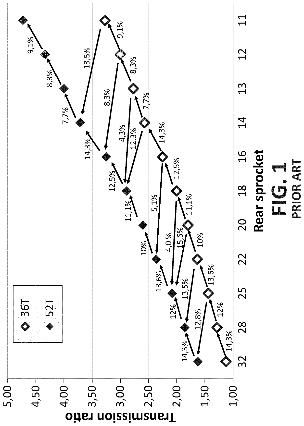
The critical point in this shifting strategy is the chain-ring shift, which involves a simultaneous shift of 2 or 3 sprockets in order to maintain a reasonable “jump” between transmission ratios, so it is a complex, slow and prone to failure operation.
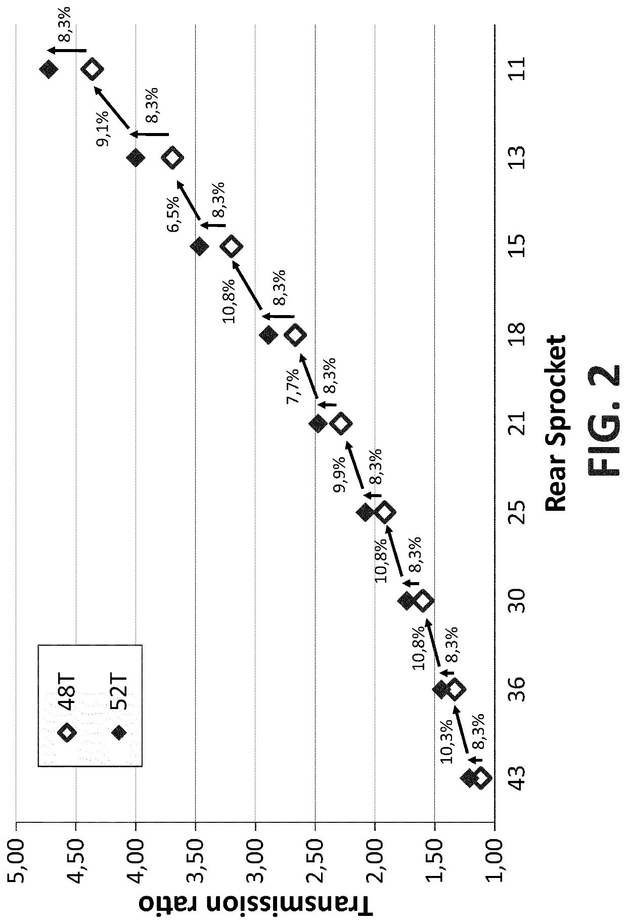
This shifting strategy presents a better staggering of gear ratios and a simpler and clearer shifting logic, however it requires using the chain-ring shifter at each gear change, which is a great limitation due to the chain-ring shifters available nowadays.
This solution for avoiding the front derailleur has great acceptance in the market, however the number of gear ratios is limited to the number of sprockets.
However, this system requires the chain to be rolling in stage III of settlement, since synchronization between different gears is not optimal.
The main limitation of this disclosure is that, due to the flexibility of the sprockets, rigidity and strength problems arise in the power transmission.
The disclosure U.S. Pat. No. 5,152,720 A solves this problem by rigid sprockets with an articulated 90-degree section that operates in the same way as the prior disclosure and is valid for changing sprockets as well as for shifting chain-rings, but stage III of shifting is not optimal yet.
But because of the displaced flank, the power transmission from tooth to chain is far from being perpendicular to the chain-ring radius at that point, so it is not performed effectively.
In addition, it compromises the support of the chain in the next tooth, unless this is also lowered, which delays the settlement of the chain in the teeth (stage III) and the time when the chain is engaged at an appropriate tooth-point for effective force transmission.
This can generate wear and noise due to a large folding between links in chain-ring shifting zone which can cause additional problems when the chain has to leave the chain-rings.
These problems in the settlement and power transmission come from a non-optimal angular synchronization between chain-rings because all segments should form a continuous solution when put together.
Another limitation of the device presented in CH-617,992-A5 is that the segments have to travel to the same plane of the previous chain-ring, keeping the same working plane, so the allowable size difference between successive chain-rings depends on the tooth height.
However, this embodiment is not recommended because on the one hand the teeth support seems very weak as illustrated in FIG. 7 and on the other hand the height of the teeth is also somewhat low which can present problems in retaining the chain in the presence of vibrations or other external forces, especially considering that the disclosure does not include any measure to improve the stability of the chain on the chain-ring in the absence of a derailleur.
In addition to structural problems when the size difference between chain-rings is low, the system presented in CH-617,992-A5 has additional structural limitations regarding the guiding of the segments and their force transmission capacity, as well as regarding the segment actuators as described in US-2014 / 0248982-A1.
However, it provides neither a solution to the limitation of synchronization of segments and chain-rings (extended stage III of shifting) nor a structural solution to use chain-rings with four teeth or less difference with guarantee.

