
Equipment mounting system

a technology for mounting systems and equipment, applied in the field of retaining systems, can solve the problems of difficult access from the end of the vehicle or over the side, difficult to readjust the system, cumbersome loading or unloading of skis and snowboards, etc., and achieve the effect of easy removal and easy movement or removal of equipment stored therein

Active Publication Date: 2022-04-19
STILLWATER CONSULTING LLC
View PDF67 Cites 3 Cited by
  • Summary
  • Abstract
  • Description
  • Claims
  • Application Information

AI Technical Summary

Benefits of technology

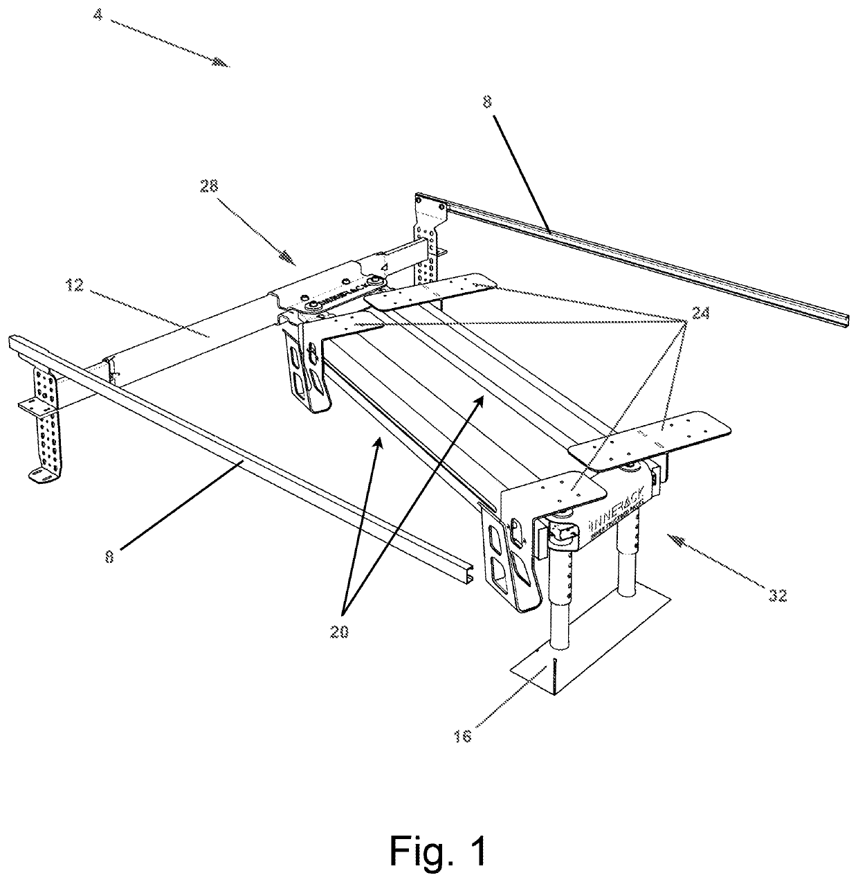
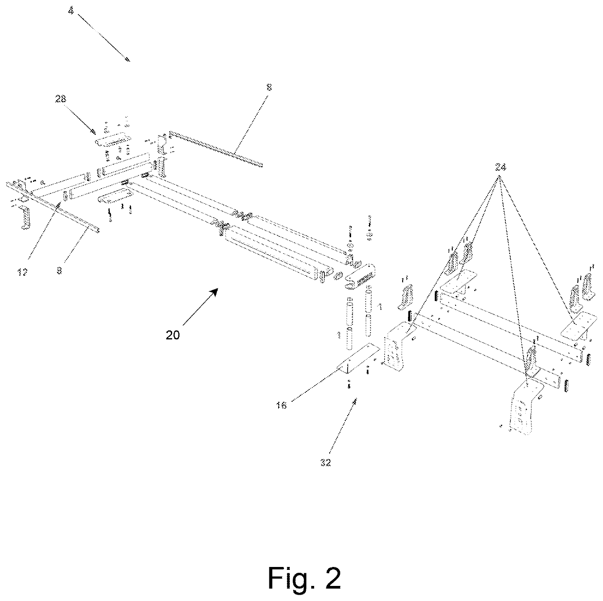
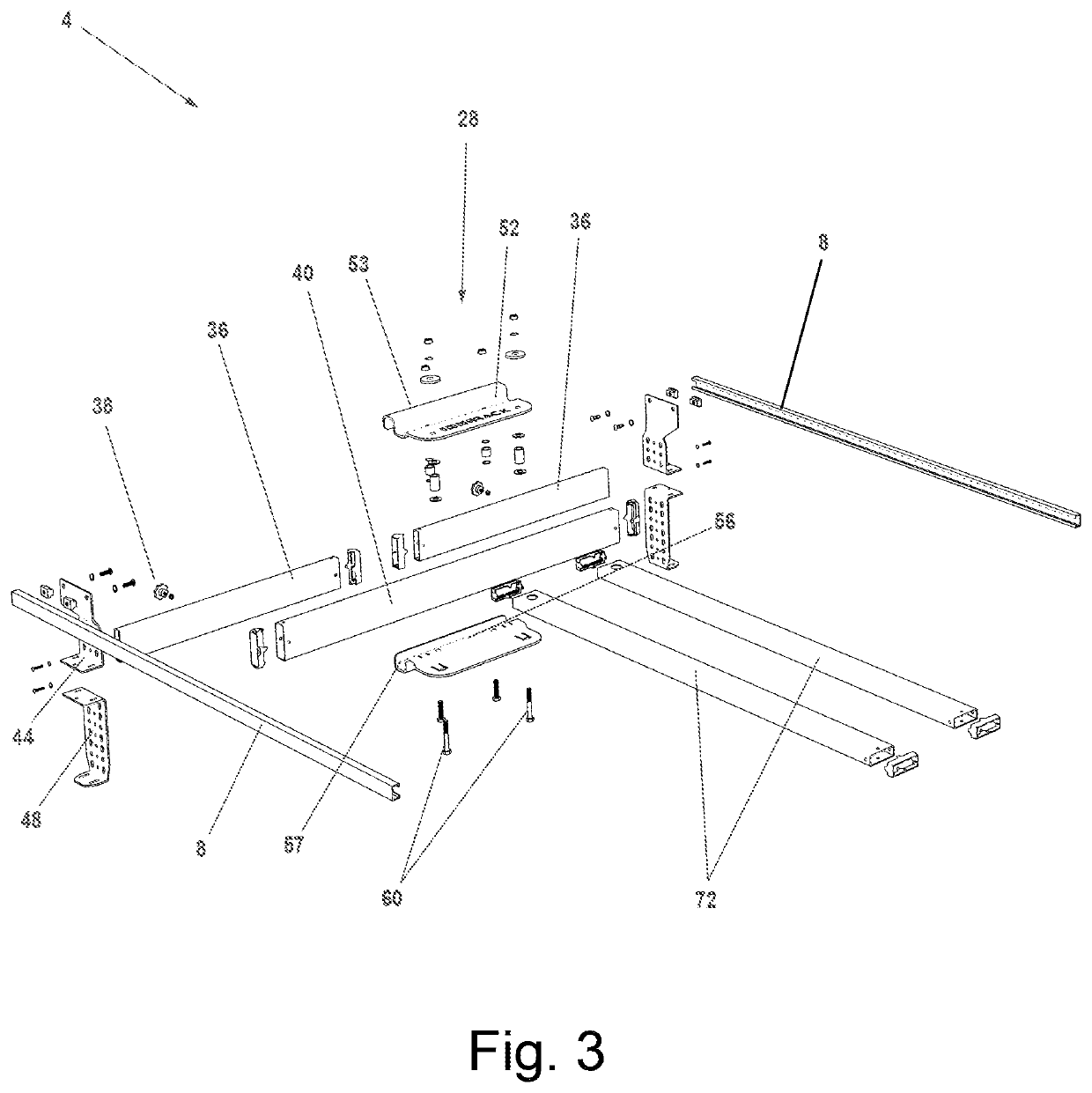
The present invention solves problems in the prior art by providing a mounting system for vehicles that allows for easy transportation and storage of long items. The system utilizes pivoting, retracting, extending, and vertical lift to fit items diagonally into truck beds or cargo vehicles. The system can be installed in a truck bed and allows for the use of a bed cover or tonneau cover for safety. The system and attached equipment can be easily removed and re-attached to a secondary mounting location for safe storage. The patent describes the technical effects of the invention and provides details on its features.

Problems solved by technology

Often these mounting systems are fixed in place, and do not allow for easy readjustment of the system when the system is used to mount different or oversized items.
However, skis and snowboards can be cumbersome to load or unload from the mounting systems; in addition, it may be desirable to mount skis so that they are not easily seen, for example within the bed of a truck or the cargo area of a van.
This can be difficult because many skis are too long to fit within the bed of a truck or the cargo area of a van with traditional fixed mounting systems that hold them parallel to the length of the storage area.
If the skis and snowboards fit in the bed of the truck or storage area of the van, then they can be hard to access from the end of the vehicle or over the side.
These conventional types of racks pose an inherent problem as most of them are not compatible with tonneau-type bed covers that either fold as panels or roll up towards the cab of the pickup truck.
These racks are also restricted to an installed position at a straight alignment relative to the vehicle so that equipment mounts in one direction—front to back, so longer equipment overhangs outside the footprint area of the truck bed.
This traditional mounting method can be unsafe or pose hazards because it is limited to holding long equipment outside the truck bed and extending beyond the vehicle's length.
Other common rack solutions that pose inherent problems are those which are installed onto the roof of vehicles where they are difficult to reach and access equipment thereon.
Such systems also leave the equipment exposed and unprotected from the elements.
These aforementioned systems fail to meet the needs of the industry because it is difficult for the user to reach mounted equipment, and it is dangerous if the user attempts to climb up onto the vehicle or the vehicle's tires to access equipment mounted on a rooftop-style rack or attempts to climb into the back of a pickup truck to access equipment.

Method used


Image

  • Equipment mounting system
  • Equipment mounting system
  • Equipment mounting system

Examples


Embodiment Construction

[0051]The following description is not to be taken in a limiting sense but is made merely for the purpose of describing the general principles of exemplary embodiments, no limitation of the scope of the invention is thereby intended. The phrases: “in one embodiment,”“in an embodiment,” and similar language such as throughout this specification may, but do not necessarily, all refer to the same embodiment. The phrases “at least one,”“one or more,” and “and / or” are open-ended expressions that are both conjunctive and disjunctive in operation. The terms “a” or “an” entity refers to one or more of that entity. As such, the terms “a” (or “an”), “one or more” and “at least one” can be used interchangeably herein. It is also to be noted that the terms “comprising,”“including,” and “having” can be used interchangeably. The described features, structures, methods, steps, or characteristics of the present disclosure may be combined in any suitable manner in one or more embodiments. In other i...


PUM


Abstract

A mounting system utilizing multidirectional pivoting, retracting, extending, and vertical lift to allow it to fit longer items diagonally into truck beds, cargo vehicles, mobile trailers, or other vehicles; and making moving or removing the equipment stored therein much easier. The mounting system is also designed to be installed inside the bed of a truck and still allow for a “bed cover” or tonneau cover to be used over the mounting system so that the mounting system and equipment mounted therein remain safely inside the vehicle. The mounting system and attached equipment can easily be removed while not in use and re-attached to secondary mounting location for safe storage.

Description

CROSS REFERENCE TO RELATED APPLICATIONS[0001]This application claims the benefit of U.S. Provisional Patent Application No. 63 / 031,675, filed on May 29, 2020, also titled “Equipment Mounting System” which is incorporated by reference herein in its entirety for all purposes.BACKGROUND OF THE INVENTION1. Field of the Invention[0002]The present invention relates to retaining systems, and more particularly to equipment stowing and retaining systems for attaching and retaining sporting equipment on a vehicle.2. Description of Related Art[0003]“Racks” and other mounting systems for mounting items to vehicles are well known in the art. These systems typically attach to rails, hard mounts, or other attachment points on a vehicle. Often these attachment points are positioned on the roof, or on the top of the perimeter of the bed of a truck. Often these mounting systems are fixed in place, and do not allow for easy readjustment of the system when the system is used to mount different or overs...

Claims


Application Information

Patent Timeline
Patent Type & Authority Patents(United States)
IPC IPC(8): A47B81/00B60R9/08A47B45/00
CPCA47B81/00A47B45/00B60R9/08B60R9/12B60R9/06
Inventor MCCARDLE, CHRISTOPHER LANCEWICKEN, GREGG ALLEN
Owner STILLWATER CONSULTING LLC
Learn More