
Drive unit for a drum motor, drum motor, rear flange and production method

a technology of drive unit and drum motor, which is applied in the direction of mechanical energy handling, manufacturing dynamo-electric machines, and supporting/enclosed/casings, etc., can solve problems such as large damage, and achieve the effect of improving existing solutions, cost-effective and/or reliable solutions

Active Publication Date: 2022-04-19
INTERROLL HLDG
View PDF124 Cites 0 Cited by
  • Summary
  • Abstract
  • Description
  • Claims
  • Application Information

AI Technical Summary

Benefits of technology

[0006]It is, therefore, an object of the present disclosure to specify a drive unit for a drum motor, a drum motor, a rear flange, a method for producing an electric drive unit, and a method for producing a drum motor which improve existing solutions. It is an object of the present invention to provide a drive unit for a drum motor, a drum motor, a rear flange, a method for producing an electric drive unit, and a method for producing a drum motor, which enable a cost-effective and / or reliable solution, the latter in particular with a view to foodstuff safety. It is furthermore an object of the present invention to provide a drive unit for a drum motor, a drum motor, a rear flange, a method for producing an electric drive unit, and a method for producing a drum motor, which enable a particularly compact construction mode.

Problems solved by technology

Oil leakages from drive units of drum motors can cause great damage, especially in the foodstuff sector.

Method used


Image

  • Drive unit for a drum motor, drum motor, rear flange and production method
  • Drive unit for a drum motor, drum motor, rear flange and production method
  • Drive unit for a drum motor, drum motor, rear flange and production method

Examples


Embodiment Construction

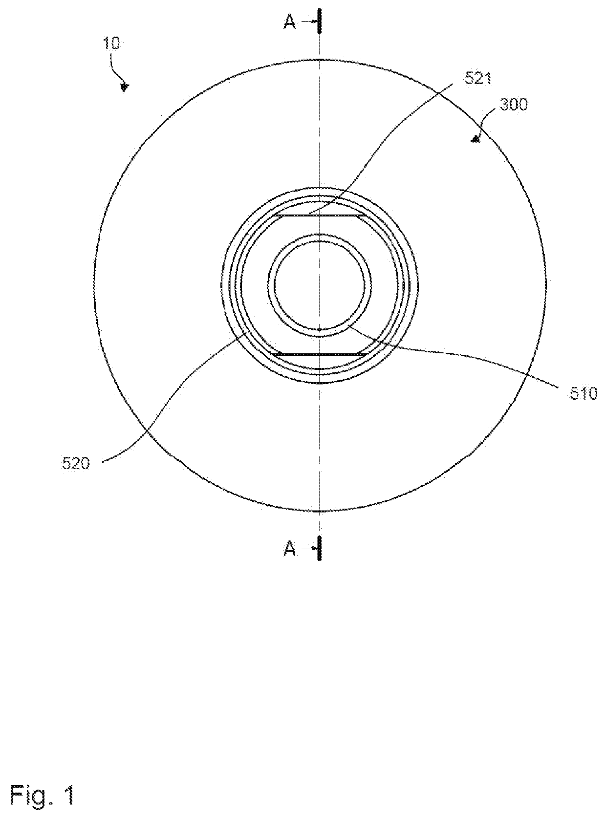
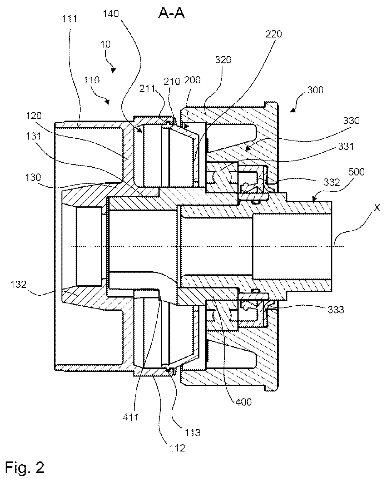
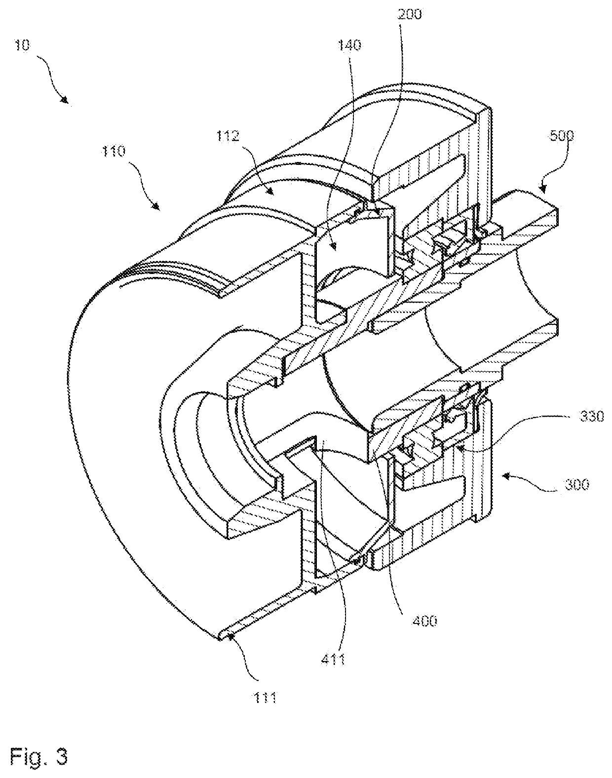
[0052]An exemplary embodiment of a rear flange 10 according to the invention, having a head element 300 is illustrated in FIGS. 1 to 3. The rear axle 500 and the intermediate tube 400 of the rear flange 10 of FIGS. 1 to 3 are illustrated separately in a three-dimensional manner in FIGS. 4 and 5. FIG. 6 shows the rear flange 10 and the head element 300 in the installed state in a drum motor 1.

[0053]The rear flange 10 comprises a main body 110 and a cover element 200. An annular space 140 is configured between an axially and radially outer wall 112 of the main body 110 of the rear flange 10 and the cover element 200. The annular space 140 is disposed and configured for receiving a cable (not illustrated in FIGS. 1 to 5) having a liquid encapsulation (not illustrated in FIGS. 1 to 5). The cover element 200 on the axially inner end 210 thereof has a radially outward pointing protrusion 211, which engages in a corresponding clearance 113 on the axially and radially outer wall 112 of the ...


PUM


Abstract

An electric drive unit comprises an electric drive device having a stator and a rotor, the stator and the rotor being disposed in a stator housing which extends along a longitudinal axis, a cable, wherein a first portion of the cable is connected to the drive device, and a liquid encapsulation is disposed on a second portion of the cable which has individual lines which are litz wires. A rear flange at an end side that faces away from an interior of the stator housing and has an annular space disposed on one end of the stator housing, wherein the liquid encapsulation is disposed in the annular space.

Description

CROSS-REFERENCE TO FOREIGN PRIORITY DOCUMENT[0001]The present application claims the benefit under 35 U.S.C. §§ 119(b), 119(e), 120, and / or 365(c) of PCT / EP2017 / 065885 filed Jun. 27, 2017, which claims priority to German Application No. 102016112036.7 dated Jun. 30, 2016.FIELD OF THE INVENTION[0002]The disclosure relates to an electric drive unit for a drum motor, in particular, for a drum motor for conveyor systems for conveying containers, pallets, and the like, for example, in the foodstuff industry. The disclosure furthermore relates to a drum motor, to a rear flange for an electric drive unit of a drum motor, to a method for producing an electric drive unit for a drum motor, and to a method for producing a drum motor.BACKGROUND OF THE INVENTION[0003]Drum motors of the type mentioned at the outset and the drive units thereof are used in conveyor systems which, apart from drum motors, often also have conveyor rollers without an electric drive unit. Depending on the application, a...

Claims


Application Information

Patent Timeline
Patent Type & Authority Patents(United States)
IPC IPC(8): H02K5/22H02K15/14H02K5/04H02K5/10H02K11/00H02K7/116H02K7/14H02K5/16
CPCH02K5/225H02K5/04H02K5/10H02K7/116H02K7/14H02K11/00H02K15/14H02K5/161H02K2207/03H02K3/50
Inventor MANS, ERWINVAN HOLTHE TOT ECHTEN, JURRIAEN
Owner INTERROLL HLDG
Learn More