Control method of multi-antenna module

a control method and antenna technology, applied in the direction of power management, transmission monitoring, receipt monitoring, etc., can solve the problems of limited antenna efficiency, difficult to achieve the effect of generating signals in the first frequency band by using the second group, and unable to achieve favorable performance. performance and increase the effect of antenna efficiency

Active Publication Date: 2022-05-03
GIGA BYTE TECH CO LTD
View PDF25 Cites 1 Cited by
  • Summary
  • Abstract
  • Description
  • Claims
  • Application Information

AI Technical Summary

Benefits of technology

[0017]Based on the above, in the control method of the multi-antenna module according to the embodiments of the disclosure, by detecting the performance of the antennas in the first frequency band and the second frequency band, the antennas are divided into the first group whose performance is better in the first frequency band than in the second frequency band and the second group other than the first group. Then, the first group is instructed to generate signals in the first frequency band, and the second group is instructed to generate signals in the second frequency band. In this way, the control method of the multi-antenna module according to the embodiments of the disclosure is able to ensure that the antennas have favorable performance in the first frequency band. In addition, since the contribution of the second group to the first frequency band is limited, the increase in antenna efficiency through generating signals in the first frequency band by using the second group is limited. In the control method of the multi-antenna module according to the embodiments of the disclosure, the second group is used to generate signals in the second frequency band. Thus, the antennas may operate in multiple frequency bands.

Problems solved by technology

Meanwhile, how to configure multiple antennas to provide favorable performance remains an issue to work on.
In addition, since the contribution of the second group to the first frequency band is limited, the increase in antenna efficiency through generating signals in the first frequency band by using the second group is limited.

Method used


Image

  • Control method of multi-antenna module
  • Control method of multi-antenna module
  • Control method of multi-antenna module

Examples


Embodiment Construction

[0023]Reference will now be made in detail to the present preferred embodiments of the disclosure, examples of which are illustrated in the accompanying drawings. Wherever possible, the same reference numbers are used in the drawings and the description to refer to the same or like parts.

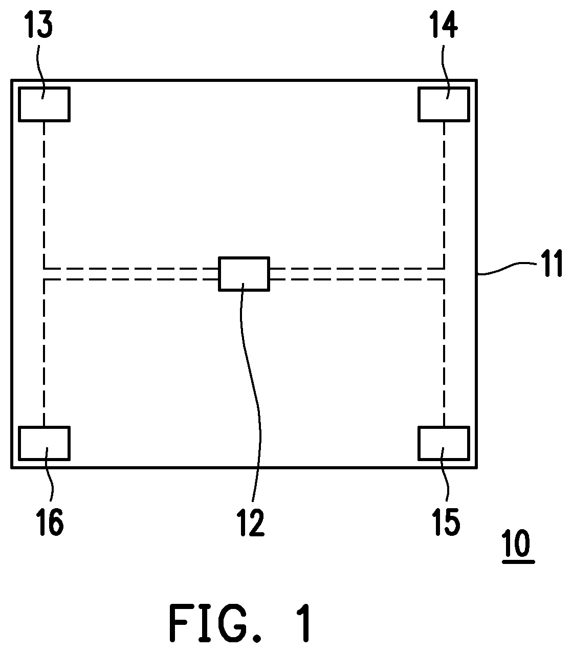
[0024]FIG. 1 is a schematic view of an electronic device according to an embodiment of the disclosure. Referring to FIG. 1, in the embodiment, an electronic device 10 is a laptop computer, a tablet computer, a cell phone, or other devices, for example. The electronic device of the embodiment includes a casing 11, an antenna control assembly 12 located in the casing 11, and a plurality of antennas 13, 14, 15, and 16 located in the casing 11. The antennas 13, 14, 15, and 16 are electrically connected with the antenna control assembly 12. In the embodiment, since the antennas 13, 14, 15, and 16 are located inside the casing 11, these antennas may be regarded as internal antennas.

[0025]In addition, whil...


PUM


Abstract

A control method of a multi-antenna module includes the following. Antennas generating signals in at least a first frequency band and a second frequency band are provided. The antennas are divided into a first group and a second group by detecting performance of the antennas in the first frequency band and the second frequency band. Antennas of the first group have better performance in the first frequency band than in the second frequency band, and antennas of the second group are antennas other than the antennas of the first group. The number of the antennas of each of the first group and the second group is at least greater than or equal to 2. The first group is instructed to generate the signals in the first frequency band, and the second group is instructed to generate the signals in the second frequency band.

Description

CROSS-REFERENCE TO RELATED APPLICATION[0001]This application claims the priority benefit of Taiwan application serial no. 109117952, filed on May 29, 2020. The entirety of the above-mentioned patent application is hereby incorporated by reference herein and made a part of this specification.BACKGROUNDTechnical Field[0002]The disclosure relates to a control method, and particularly relates to a control method of a multi-antenna module.Description of Related Art[0003]Through the progress of wireless technologies, electronic devices with multiple antennas have been quite common. Meanwhile, how to configure multiple antennas to provide favorable performance remains an issue to work on.SUMMARY[0004]Embodiments of the disclosure provide a control method of a multi-antenna module capable of generating signals of multiple frequency bands.[0005]A control method of a multi-antenna module according to an embodiment of the disclosure includes the following. A plurality of antennas are provided....

Claims


Application Information

Patent Timeline
Patent Type & Authority Patents(United States)
IPC IPC(8): H04B1/00H04B17/27H04B7/08H04W52/28H04B7/06
CPCH04B1/0064H04B7/0691H04B7/0874H04B17/27H04W52/283H01Q1/245H01Q5/307H04B1/401H04B1/3833H04B1/50H04B17/318H04B17/336
Inventor HUANG, CHING-HSUNLIAO, TSE-HSIEN
Owner GIGA BYTE TECH CO LTD
Why Eureka
Try Eureka