Light irradiation device

a technology of light irradiation and cooling medium, which is applied in the direction of disassembly/discharge, volume/mass flow by differential pressure, and dispersion of fluids by mechanical effects, etc., can solve the problems of light irradiation devices, and achieve the effect of improving the cooling efficiency, increasing the flow velocity of the cooling medium, and increasing the cooling efficiency

Active Publication Date: 2022-05-10
USHIO DENKI KK
View PDF2 Cites 0 Cited by
  • Summary
  • Abstract
  • Description
  • Claims
  • Application Information

AI Technical Summary

Benefits of technology

[0010]For this reason, the temperature of the cooling water W10 flowing through the second flow channel F20 has already increased before absorption of heat from the LEDs 111, which makes it difficult to absorb heat from the LEDs 111 and reduces the efficiency of cooling the LEDs 111. As the result, the luminous efficacy of the LEDs 111 may be reduced and the illuminance of the light irradiation device 100 may be reduced.
[0051]According to the present invention, it is possible to achieve a light irradiation device having improved cooling efficiency.

Problems solved by technology

The present inventors have studied such a light irradiation device as described above for use in sterilizing a fluid in a container or tank or for photochemical treatment, and as a result, have found that the light irradiation device has a problem as described below.

Method used


Image

  • Light irradiation device
  • Light irradiation device
  • Light irradiation device

Examples


Embodiment Construction

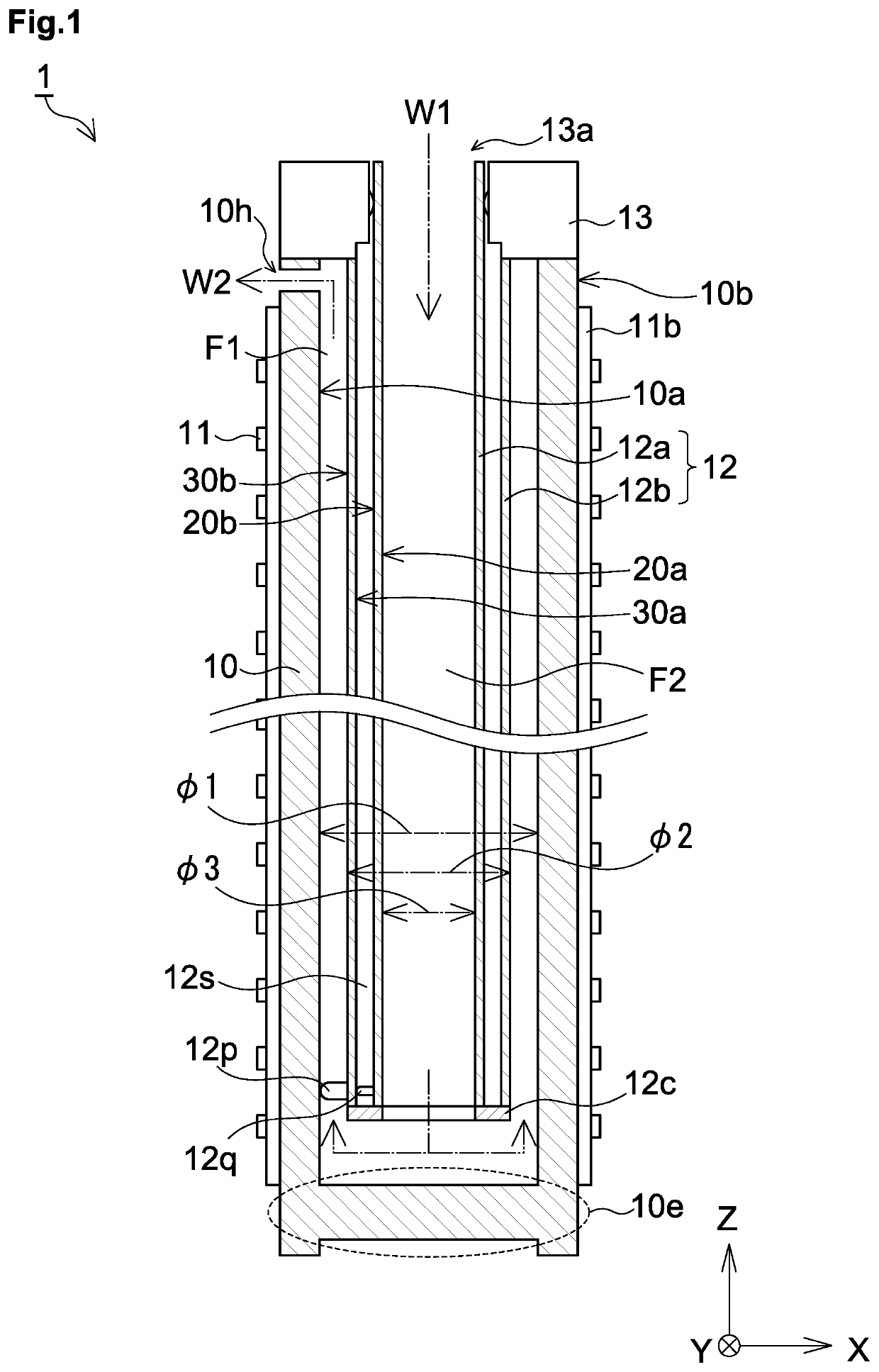
[0063]Hereinbelow, a light irradiation device according to the present invention will be described with reference to the drawings. It is to be noted that all the drawings are schematically shown, and the size ratio between components and the number of components in each of the drawings are not always the same as the actual size ratio and number.

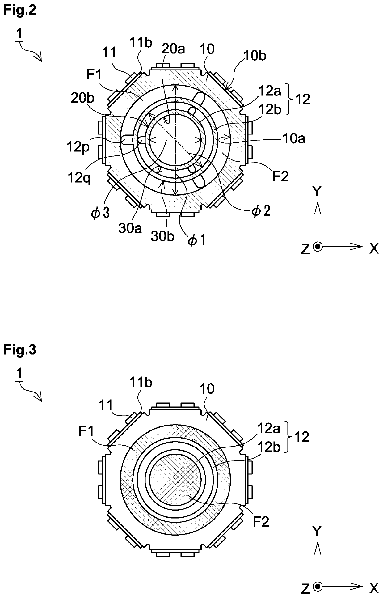
[0064]FIG. 1 is a schematic sectional side view of an embodiment of a light irradiation device 1. FIG. 2 is a sectional view of the light irradiation device 1 shown in FIG. 1 taken along an XY plane at a predetermined Z coordinate. Similarly to the above description, also in the following description, the axial direction of a light source supporter 10 is defined as a Z direction, and a plane orthogonal to the Z direction is defined as an XY plane. When a distinction is made between a positive direction and a negative direction to express a direction, a positive or negative sign is given like “+Z direction” or “−Z direction”, and when a direct...


PUM

PropertyMeasurementUnit
angleaaaaaaaaaa
diameteraaaaaaaaaa
diameteraaaaaaaaaa

Abstract

The light irradiation device includes a light source supporter having a tubular shape is closed on a side of one end, a plurality of light-emitting elements placed on an outer wall surface of the light source supporter, a tubular body extending inside the light source supporter in an axial direction of the light source supporter, a first flow channel formed between the tubular body and the light source supporter and having an annular shape when viewed from the axial direction; and a second flow channel formed inside the tubular body, wherein the first flow channel and the second flow channel communicate with each other on a side of one end of the light source supporter, and the tubular body contains a material having a thermal conductivity lower than a thermal conductivity of a material constituting an outer wall of the first flow channel.

Description

BACKGROUND OF THE INVENTIONField of the Invention[0001]The present invention relates to a light irradiation device, particularly relates to a light irradiation device that applies light with LED elements.Description of the Related Art[0002]As a light source for sterilizing a fluid in a container or tank or for photochemical treatment, for example, a long light irradiation device as disclosed in the following Patent Document 1, which includes a plurality of LEDs as a light source and extends in one direction, is known.PRIOR ART DOCUMENTPatent Document[0003]Patent Document 1: JP-A-2017-143971SUMMARY OF THE INVENTION[0004]The present inventors have studied such a light irradiation device as described above for use in sterilizing a fluid in a container or tank or for photochemical treatment, and as a result, have found that the light irradiation device has a problem as described below. Hereinbelow, a description will be made with reference to the drawings.[0005]When electric power is su...

Claims


Application Information

Patent Timeline
Patent Type & Authority Patents(United States)
IPC IPC(8): A61L2/08G01F1/37A61L2/10
CPCA61L2/08A61L2/10G01F1/37A61L2202/122A61L2202/11
Inventor MURAKAMI, SATOSHIKANAHASHI, YOSHIHIRO
Owner USHIO DENKI KK
Why Eureka
Try Eureka