
Method and device for the production of an optimized neck contour on preforms

a neck contour and preform technology, applied in the field of ##d and apparatus for the production of an optimized neck contour on preforms, can solve the problems of . its sealing function, loss of complex capabilities of the closing system, and unnecessary material consumption

Active Publication Date: 2022-05-10
AKTAS MAHIR
View PDF10 Cites 0 Cited by
  • Summary
  • Abstract
  • Description
  • Claims
  • Application Information

AI Technical Summary

Benefits of technology

This approach enables more efficient heat transfer and material stretching during blow-molding, reducing raw material consumption and preventing sink marks, while maintaining the sealing function of the neck region, thus improving the quality of the final bottle product.

Problems solved by technology

The neck region must not undergo any further alteration above the transporting ring during the blow-molding process, since otherwise there is a risk of the closure system losing its complex capabilities, e.g. its sealing function.
In most cases, this means, that as a result of a gradual temperature transition, the material beneath the transporting ring cannot be optimally drawn off into the bottle body during the stretch-blow-molding process, and this results in unnecessary material consumption.
In the case of the conventional quick production cycles, there is a considerable amount of residual heat remaining in the interior of the preform wall, and this leads to reheating, as a result of which the preform can soften again and crystallize, which can render it unusable.
If the material freezes prematurely as a result of thinner wall thicknesses in the injection region or in the neck region, it is not possible to avoid shrinkage in the cooling phase as a result of the melt being subjected to holding pressure, this having an effect on the entire preform including the neck region, and this all consequently results in undesired sink marks in critical regions of the preform, particularly in the neck region.

Method used


Image

  • Method and device for the production of an optimized neck contour on preforms
  • Method and device for the production of an optimized neck contour on preforms
  • Method and device for the production of an optimized neck contour on preforms

Examples


Embodiment Construction

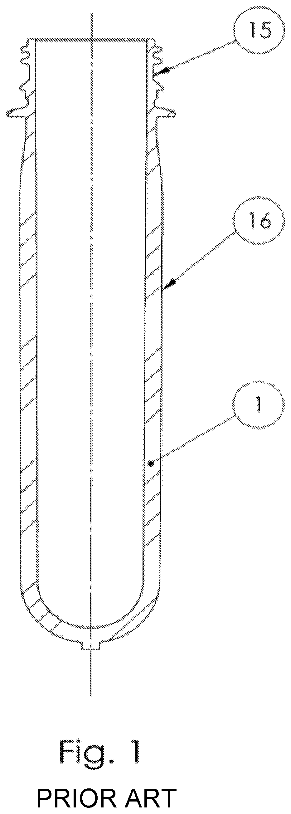
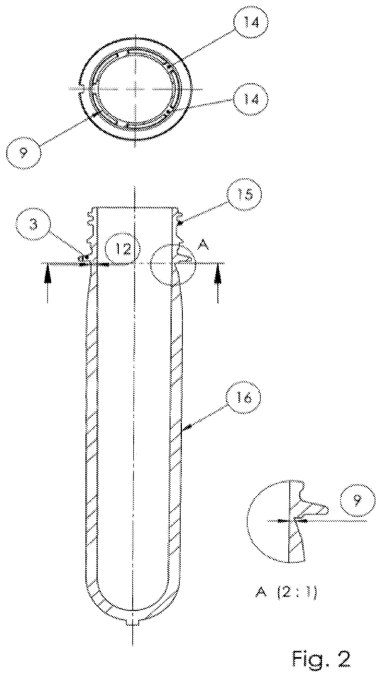
[0031]FIG. 1 shows a preform produced according to the prior art. Said preform may have a transporting ring 3 for further container-production steps—it may also be possible in the future, however, to dispense with said transporting ring 3, since it is possible, if appropriate, to grip the region between the ribs of the preform. The wall thickness in the region beneath the transporting ring 3 here has a similar wall thickness 12 as the threaded region 15. On account of the risk of the melt freezing, preforms according to FIG. 2, which are optimized for the blow-molding process by having reduced wall thicknesses 9 beneath the transporting ring 3, can be realized by injection molding only with limited success, since it is then no longer possible for the holding pressure, which counteracts the shrinkage of the preform during the cooling process, to act in the critical regions.

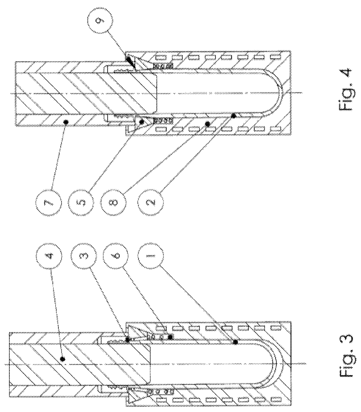
[0032]This invention discloses three solution-related approaches as to how the preform in FIG. 2 can be produced...


PUM

PropertyMeasurementUnit
temperatureaaaaaaaaaa

Abstract

A method and device for producing an optimized neck contour on preforms below the neck which is optimal for subsequent stretch blow molding. The geometry has a significantly thinner wall thickness than the neck itself. The preform can only be produced in the injection molding tool, when axial channels are used on the point or the vanes produce the thin points on the preform during injection molding. The thin-walled geometry on the preform can be produced outside of the mold during post-cooling by embossing. The preform is then removed in a cooled receiving sleeve and is cooled in the body by intensive contact cooling while no cooling contact is made with the preform neck due to the initial position of the embossing element. Due to the reheating of the neck they can be mechanically deformed into a new geometry advantageous for blow molding and thus wall thickness can be influenced.

Description

CROSS-REFERENCE TO RELATED APPLICATIONS[0001]The present application is a Continuation Application of U.S. patent application Ser. No. 16 / 448,369, filed Jun. 21, 2019, which is a Continuation Application of U.S. patent application Ser. No. 15 / 513,075, filed Mar. 21, 2017, which is a 371 of International Application PCT / DE2015 / 000472 filed on Sep. 21, 2015 which claims the benefit of priority from German Patent Application No. 10 2014 014 144.6 filed Sep. 22, 2014, the contents of each of which are incorporated herein by reference.BACKGROUND OF THE INVENTION[0002]Method and apparatus for the production of an optimized neck contour on preforms.[0003]The present invention relates to a method and an apparatus for the production of preforms for forming an advantageous neck geometry for the subsequent blow-molding process.[0004]Preforms are injection-molded blanks which are made of at least one thermoplastic material and are used in blow-molding machines for producing stretch-blow-molded ...

Claims


Application Information

Patent Timeline
Patent Type & Authority Patents(United States)
IPC IPC(8): B29C45/00B29C45/72B29B11/08B29B11/14B29C49/06B29C45/17B29C45/26B29C45/40B29C49/42B29C49/64B29K101/12B29L31/00
CPCB29C45/0055B29B11/08B29B11/14B29C45/1773B29C45/2628B29C45/2632B29C45/4005B29C45/7207B29C49/06B29B2911/1402B29B2911/1404B29B2911/14026B29B2911/14033B29B2911/1433B29B2911/14343B29C45/0081B29C49/4242B29C49/6445B29C2045/7214B29K2101/12B29L2031/7158B29C2949/26B29C2949/24B29C2949/28B29C2949/22B29C2949/0723B29C2949/0745B29C49/071B29C2949/0715B29C2049/023B29C49/42421B29C49/42422B29C49/6465B29C49/6466B29C49/6467B29C49/76
Inventor AKTAS, MAHIR
Owner AKTAS MAHIR
Learn More