Galvanically decorated component and method for producing a galvanically decorated component

a technology of galvanic decoration and component, applied in the direction of superimposed coating process, liquid/solution decomposition chemical coating, coating, etc., can solve the problems of increasing the cost of the additional work step, the symbol produced from metal does not demonstrate sufficient strength against wear and corrosion, and the cost is significantly increased

Inactive Publication Date: 2020-07-30
GERHARDI KUNST
View PDF0 Cites 0 Cited by
  • Summary
  • Abstract
  • Description
  • Claims
  • Application Information

AI Technical Summary

Benefits of technology

[0008]This is where the invention wishes to provide a remedy. The invention is based on the task of creating a method for the production of a component decorated by electroplating, having a symbol introduced into the surface using laser-activated thermal transfer imprinting, preferably a symbol or structure through which light can pass, in which method the component is produced from a plastic that can be electroplated, using the injection-molding method, which component is, on the one hand, cost-advantageous and also suitable for the production of mass-produced products, but on the other hand also makes the required wear resistance of the respective operating elements available even without additional treatment.

Problems solved by technology

However, it has proven to be problematical that the symbol produced from metal does not demonstrate sufficient strength against wear and corrosion without an additional protective layer.
However, the costs are significantly increased by this additional work step.
However, the method has the disadvantage that for one thing, the additional work step of laser use for production of the symbol increases the costs.
Furthermore, the symbols are exposed down to the plastic material of the unfinished part, and this can lead to problems in the event of subsequent contact with cosmetics, in particular sun creams, since the plastic materials used are not or only conditionally resistant.
In total, the method is not well suited for mass-production components because of the method sequences that exist.

Method used


Image

  • Galvanically decorated component and method for producing a galvanically decorated component

Examples


Embodiment Construction

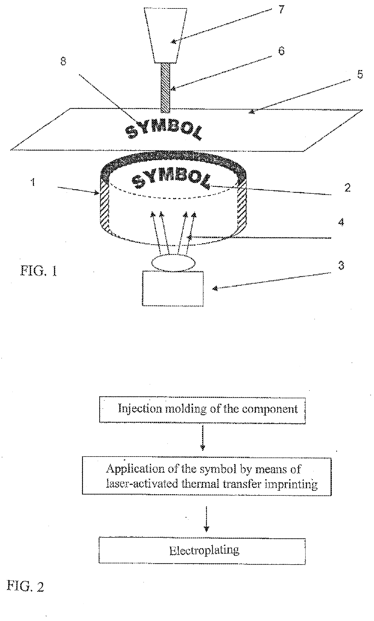
[0020]The coated component 1, shown as an exemplary embodiment, shows a product produced from plastic for the automotive industry, with subsequent electroplating. The component 1, after completion of the method, has a symbol 2, which can be both pictograms and numbers, words or the like.

[0021]In the exemplary embodiment according to FIG. 1, a start / stop button for an automobile is described, with which the engine of the automobile can be started and shut off again. In this case, the symbol consists of the words “start,”“stop,” and “engine.” If other operating elements are involved, the symbol is generally formed in the form of a pictogram, for example the representation of a headlight, if an operating element for vehicle lighting is involved.

[0022]In the method according to the exemplary embodiment according to FIG. 2, first the component to be produced from plastic is produced using the injection-molding method. The plastic is preferably a plastic that can be electroplated, prefera...


PUM

PropertyMeasurementUnit
thicknessaaaaaaaaaa
thicknessaaaaaaaaaa
translucentaaaaaaaaaa

Abstract

A method for producing a galvanically decorated component with a symbol or structure of a transilluminatable design incorporated in the surface produces the component from an electroplatable plastic in an injection-molding process, and the symbol or structure is produced from a non-electroplatable, electroplating-resistant printed image. The printed image is transferred from a carrier onto the component using thermal transfer by being activated using a laser. A galvanically decorated component is produced by the method.

Description

CROSS REFERENCE TO RELATED APPLICATIONS[0001]This application is a divisional of and Applicant claims priority under 35 U.S.C. §§ 120 and 121 of U.S. application Ser. No. 15 / 754,705 filed on Feb. 23, 2018, which application is a national stage application under 35 U.S.C. § 371 of PCT Application No. PCT / EP2016 / 070578 filed on Sep. 1, 2016, which claims priority under 35 U.S.C. § 119 from German Patent Application No. 20 2015 006 095.1 filed on Sep. 3, 2015, the disclosures of each of which are hereby incorporated by reference. A certified copy of priority German Patent Application No. 20 2015 006 095.1 is contained in parent U.S. application Ser. No. 15 / 754,705. The International Application under PCT article 21(2) was not published in English.BACKGROUND OF THE INVENTION1. Field of the Invention[0002]The invention relates to a method for the production of a component decorated by electroplating, having a symbol or structure introduced into the surface, through which light can pass, ...

Claims


Application Information

Patent Timeline
Patent Type & Authority Applications(United States)
IPC IPC(8): C25D5/56C25D5/02
CPCC25D5/56C25D5/022C23C28/00B29C37/00B32B27/06B32B15/08Y10T428/24917C23C18/1641C23C18/1605
Inventor KIESLICH, DIRKHU, BINFENG
Owner GERHARDI KUNST
Why Eureka
Try Eureka