
Power supply circuit breaker device

a technology of power supply circuit and breaker device, which is applied in the direction of coupling contact member, coupling device connection, transportation and packaging, etc., can solve problems such as power supply circuit breakage, and achieve the effect of reducing static friction force and improving operability

Active Publication Date: 2022-05-10
YAZAKI CORP
View PDF15 Cites 0 Cited by
  • Summary
  • Abstract
  • Description
  • Claims
  • Application Information

AI Technical Summary

Benefits of technology

This configuration reduces static friction and improves the operability of the power supply circuit breaker device by lowering the contact pressure between main terminals, making the breaking operation more efficient and requiring less force.

Problems solved by technology

Next, after an operator operates a release operation unit to release the locking state or the locking part, the lever is rotated to the disengaging position, a strong current terminal (main terminal) is caused to be in an unconnected state, the main circuit switch is caused to be in the OFF state, and as a result, the power supply circuit is broken.

Method used


Image

  • Power supply circuit breaker device
  • Power supply circuit breaker device
  • Power supply circuit breaker device

Examples


embodiment

[0023

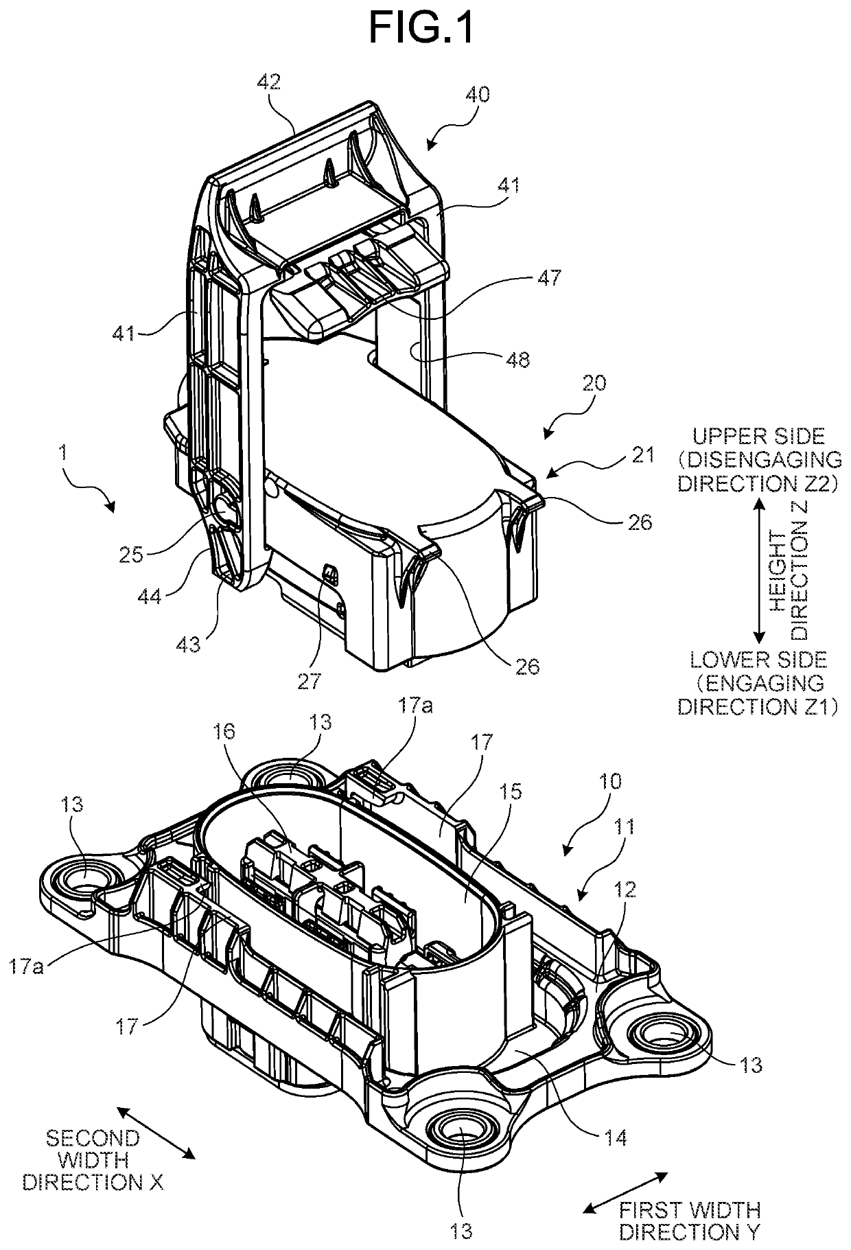
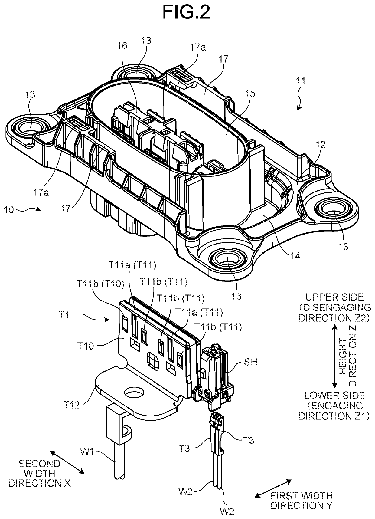
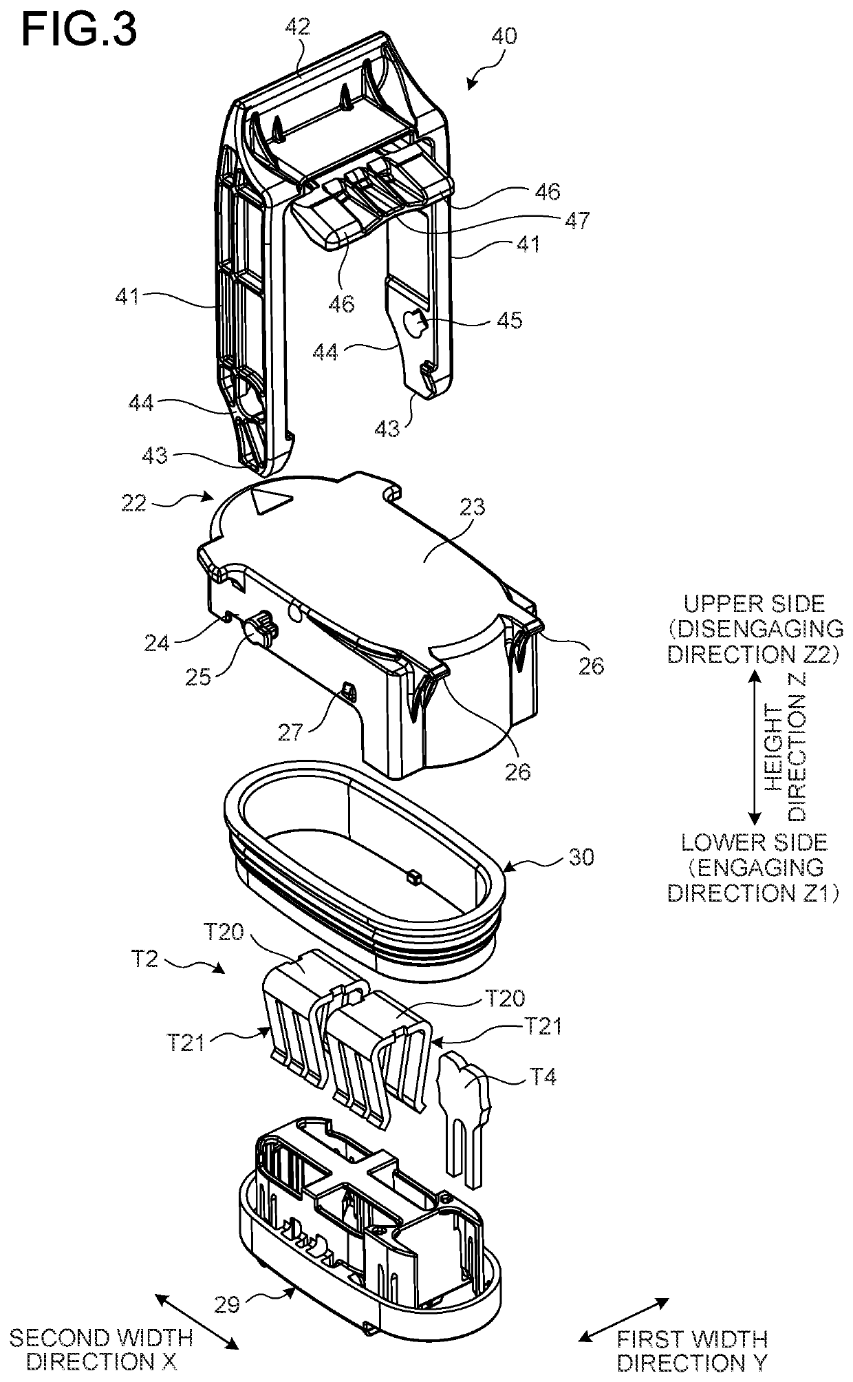
[0024]FIG. 1 is an exploded perspective view illustrating a schematic configuration of an embodiment of a power supply circuit breaker device (service plug 1) according to the present invention. FIG. 2 is an exploded perspective view of a first connector in FIG. 1. FIG. 3 is an exploded perspective view of a second connector in FIG. 1. FIG. 7 is a cross-sectional perspective view of the service plug illustrating a lock state in which rotation of a lever is temporarily regulated in a half-engaged state at the time of rotating the lever to be in a non-engaged state from a completely engaged state.

[0025]The service plug 1 as a power supply circuit breaker device according to the present embodiment is a device that is mainly mounted on a vehicle such as an electric vehicle and a hybrid vehicle, incorporated in a power supply circuit (not illustrated) for supplying power to a load unit such as a rotary electric machine from a power supply unit such as a battery, and connects (energi...


PUM


Abstract

A service plug includes first and second main terminals, first and second signal terminals, a lock part that locks a lever to a second connector housing to regulate rotation of the lever in a state in which the lever is positioned at a half-engaged position between a completely engaged position and a non-engaged position, and a lock releasing part that releases a lock state. A configuration is made such that, as the lever is rotated from the completely engaged position to the half-engaged position, part of a plurality of contact pieces of the second main terminal that is brought into elastic contact with the first main terminal at a position displaced in an approaching direction, and the other part of the contact pieces maintains elastic contact at a position that is not displaced in the approaching direction and a separating direction.

Description

CROSS-REFERENCE TO RELATED APPLICATION(S)[0001]The present application claims priority to and incorporates by reference the entire contents of Japanese Patent Application No. 2020-017777 filed in Japan on Feb. 5, 2020.BACKGROUND OF THE INVENTION1. Field of the Invention[0002]The present invention relates to a power supply circuit breaker device.2. Description of the Related Art[0003]In the related art, there is known a power supply circuit breaker device (service plug) that is mainly mounted on a vehicle such as an electric vehicle and a hybrid vehicle, incorporated is a power supply circuit for supplying power to a load unit such as a rotary electric machine from a power supply unit such as a battery, and able to connect or break the power supply circuit as needed. The power supply circuit breaker device includes a pair of main terminals functioning as a main circuit switch that switches the power supply circuit between an energizable state and a breaking state, and a pair of signa...

Claims


Application Information

Patent Timeline
Patent Type & Authority Patents(United States)
IPC IPC(8): H01R13/629H01R13/04H01R13/11B60R16/033
CPCH01R13/62955H01R13/04H01R13/113B60R16/033H01R2201/26H01R13/713H01R13/112H01R13/635H01R31/08Y02T10/70
Inventor SATO, TAKAHIKO
Owner YAZAKI CORP
Learn More