
Storage system and controller location method

a storage system and controller technology, applied in the field of storage systems, can solve the problems of data transfer between the host and the controller, degraded performance, bottlenecks, etc., and achieve the effect of improving the access performance of the storage system

Active Publication Date: 2022-05-10
HITACHI LTD
View PDF13 Cites 0 Cited by
  • Summary
  • Abstract
  • Description
  • Claims
  • Application Information

AI Technical Summary

Benefits of technology

The present invention proposes a storage system that improves access performance by mitigating performance bottlenecks associated with insufficient network bands. This is achieved by minimizing the amount of data transfer using narrow band data transfer paths and optimizing controller assignment. The technical effects of this invention include improved access performance and minimized data transfer bottlenecks.

Problems solved by technology

Thus, there is a problem in that the data transfer between the host and the controller may be a bottleneck associated with insufficient bands in the network.
Additionally, in the above-described two data transfers, data transfer paths with narrow bands are likely to include insufficient bands, and thus avoidance of degraded performance of the storage system requires minimization of the amount of data transfer using a data transfer path with a narrow band.

Method used


Image

  • Storage system and controller location method
  • Storage system and controller location method
  • Storage system and controller location method

Examples


first embodiment

(1) First Embodiment

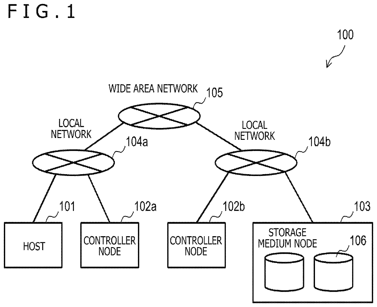
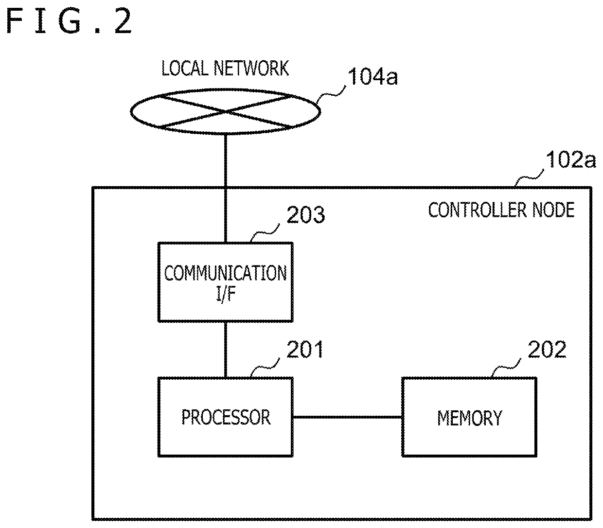
[0027]In a first embodiment of the present invention, an example of a storage system will be described. In the example, an assignment destination node to which a controller function executing access processing is assigned is determined and controlled on the basis of the amount of data transfer between a node with the controller function and a host (amount of to-and-from-host data transfer) and the amount of data transfer between the node with the controller function and a node with a storage medium (amount of to-and-from-storage-medium-node data transfer). The node to which the controller function executing access processing is assigned corresponds to a controller with an ownership for the access processing (owner controller). Note that the present embodiment is not intended to limit the scope of the present invention and that not all elements described in the present embodiment are needed to accomplish the object of the present invention.

[0028]FIG. 1 is a diagra...

second embodiment

(2) Second Embodiment

[0093]In a second embodiment of the present invention, an example of a storage system will be described. In the example, an assignment destination node of the controller function executing the access processing is determined and controlled on the basis of the amount of data transfer involved in access to a storage medium associated not only with processing resulting from to an access request from the host but also with internal processing scheduled to be implemented by the node with the controller function. Note that the present embodiment is not intended to limit the scope of the present invention and that not all the elements described in the present embodiment are needed to achieve the object of the present invention. Additionally, the description of the present embodiment focuses on differences from the configurations and the operations in the first embodiment, and components, reference signs, operations, and the like that will not be described below are ass...


PUM


Abstract

A possible performance bottleneck associated with insufficient network bands is mitigated to allow improvement of access performance of a storage system.A storage system includes a first node with a storage medium of storage and a plurality of second nodes each with a controller function for the storage, and is communicatively connected to a host providing an access request to the storage. One of the plurality of second nodes is determined to be a node to which a controller function executing access processing on the storage is assigned on the basis of a first amount of data transfer between the second node and the host and a second amount of data transfer between the second node and the first node.

Description

BACKGROUND OF THE INVENTION1. Field of the Invention[0001]The present invention relates to a storage system including nodes connected together by a network and determining assignment of a node with a controller function and a controller assignment method.2. Description of the Related Art[0002]In order to satisfy wide-range requests for access performance and storage capacity, storage systems used in recent computer environments use an architecture in which a network is used to connect a node with a controller function processing access requests to storage and a node storing a storage medium. In such a storage system, the processing performance and the storage capacity can be adjusted and added by connecting, to the network, a required number of nodes each with a controller function (controllers) and a required number of nodes each with a storage medium (storage medium nodes). Among the controllers, each node with a controller function executing access processing transfers, to and fr...

Claims


Application Information

Patent Timeline
Patent Type & Authority Patents(United States)
IPC IPC(8): H04L67/1097G06F3/06H04L67/62H04L67/63
CPCH04L67/1097G06F3/061G06F3/067G06F3/0658H04L67/325H04L67/327G06F3/0656G06F3/0649G06F3/0635G06F12/0868G06F2212/262H04L67/62H04L67/63
Inventor OGAWA, SHUGOTATSUMI, RYOSUKEOHIRA, YOSHINORIHOSOGI, KOJI
Owner HITACHI LTD
Learn More