Remote controlled moving lighting system

a technology of moving objects and remote control, applied in the field of remote control moving lighting systems, can solve the problems of many control systems for robotic lights, inability to accurately track objects in real time or near real-time, and inability to accurately shine a light on moving objects

Active Publication Date: 2022-05-17
REYES EDUARDO
View PDF20 Cites 0 Cited by
  • Summary
  • Abstract
  • Description
  • Claims
  • Application Information

AI Technical Summary

Benefits of technology

[0029]It is another object of this invention to provide a remote controlled moving lighting system that is volumetrically efficient for carrying, transporting, and storage.
[0030]It is another object of this invention to provide a remote controlled moving lighting system that can be readily assembled and disassembled without the need of any special tools.
[0031]It is another object of this invention to provide a remote controlled moving lighting system, which is of a durable and reliable construction.

Problems solved by technology

However, accurately tracking the object in real time or near real-time is difficult, and this may lead to a robotic light inaccurately attempting to shine a light on a moving object.
Moreover, it is recognized that many control systems for robotic lights are limited to controlling the direction at which a robotic light is pointing”.

Method used


Image

  • Remote controlled moving lighting system
  • Remote controlled moving lighting system
  • Remote controlled moving lighting system

Examples


Embodiment Construction

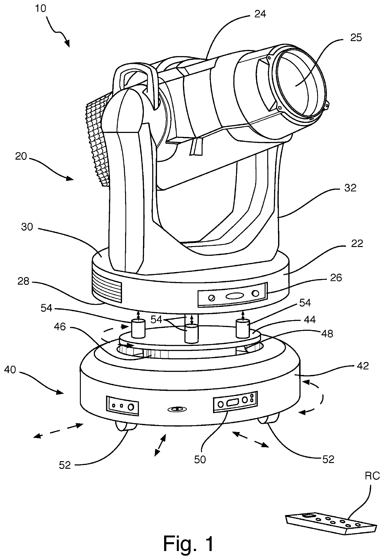
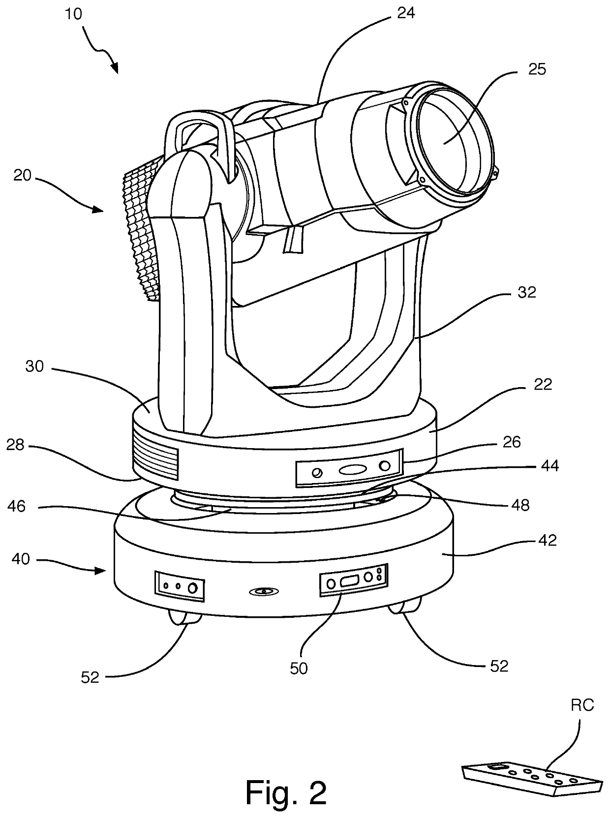
[0039]Referring now to the drawings, the present invention is a remote controlled moving lighting system, and is generally referred to with numeral 10. It can be observed that it basically includes lighting system 20 and movable base assembly 40.

[0040]As seen in FIGS. 1 and 2, lighting system 20 comprises light base 22, light housing 24, lens 25, light control panel 26, and bracket 32. Light base 22 comprises bottom face 28 and top face 30. Bracket 32 is mounted onto top face 30. It is noted that lighting system 20 can be defined as an individual theatrical lighting fixture.

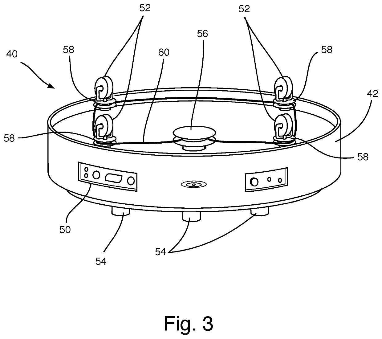
[0041]Movable base assembly 40 comprises base body 42, plate 44, plate base 46, and control panel 50. Plate 44 comprises posts 54. Base body 42 defines cavity 48 to receive plate base 46 and plate 44. Plate 44 is of a first predetermined diameter, and cavity 48 is of a second predetermined diameter, whereby the first predetermined diameter is smaller than the second predetermined diameter. Lighting system 20 is m...


PUM


Abstract

A remote controlled moving lighting system, which has a lighting system and a movable base assembly, whereby the lighting system is mounted onto the movable base assembly. The lighting system and the movable base assembly are remote controlled and battery-operated to moves on a surface. The lighting system has a light housing, a light base, a lens, a light control panel, and a bracket. The movable base assembly has a base body, a plate, and a plate base. The movable base assembly further has wheels. The lighting system mounts onto the plate of the movable base assembly. The movable base assembly and the lighting system mounted thereon are both remotely controlled independently of each other. The lighting system keeps a focus in a predetermined point while the movable base assembly is able to move in any direction.

Description

BACKGROUND OF THE INVENTION1. Field of the Invention[0001]The present invention relates to lighting systems, and more particularly, to remote controlled moving lighting systems.2. Description of the Related Art[0002]Applicant believes that one of the closest references correspond to U.S. Pat. No. 9,109,769 B2 issued to Lee on Aug. 18, 2015 for Portable cordless multipurpose lighting system. However, it differs from the present invention because Lee teaches systems and methods for lighting body panels of automobiles to facilitate repair of the body panels, where one embodiment is a portable lighting apparatus that includes a light board, a base and an extension member that connects the light board to the base. The light board is supported by the extension member, which is supported by the base. A battery in the base provides power through conductors in the extension member to light sources in the light board. A slip ring in the extension member couples the conductors together so that...

Claims


Application Information

Patent Timeline
Patent Type & Authority Patents(United States)
IPC IPC(8): F21V21/06F21V14/02F21V21/30F21V21/15F21W131/406G05D1/00G05D1/12
CPCF21V21/06F21V14/025F21V21/15F21V21/30G05D1/0011G05D1/12F21W2131/406
Inventor REYES, EDUARDO
Owner REYES EDUARDO
Why Eureka
Try Eureka