
Catheter for thromboembolic disease with mechanic waves, injection and ejection

a thromboembolic disease and mechanic wave technology, applied in the field of medical devices, can solve problems such as vibrations in or around the catheter, and achieve the effects of convenient and convenient use, convenient use, and convenient us

Active Publication Date: 2020-10-06
LORENZO EDUARDO
View PDF43 Cites 0 Cited by
  • Summary
  • Abstract
  • Description
  • Claims
  • Application Information

AI Technical Summary

Benefits of technology

This invention is about a catheter that can treat blood clotting. It has a unique design that allows it to carry and store mechanical waves, injection, and ejection efficiently. It is durable and reliable, and can be manufactured and maintained at a low cost.

Problems solved by technology

The vibration processor may provide electric signals that generate acoustic vibrations in the piezo-ceramic element, causing vibrations in or around the catheter.

Method used


Image

  • Catheter for thromboembolic disease with mechanic waves, injection and ejection
  • Catheter for thromboembolic disease with mechanic waves, injection and ejection
  • Catheter for thromboembolic disease with mechanic waves, injection and ejection

Examples


Embodiment Construction

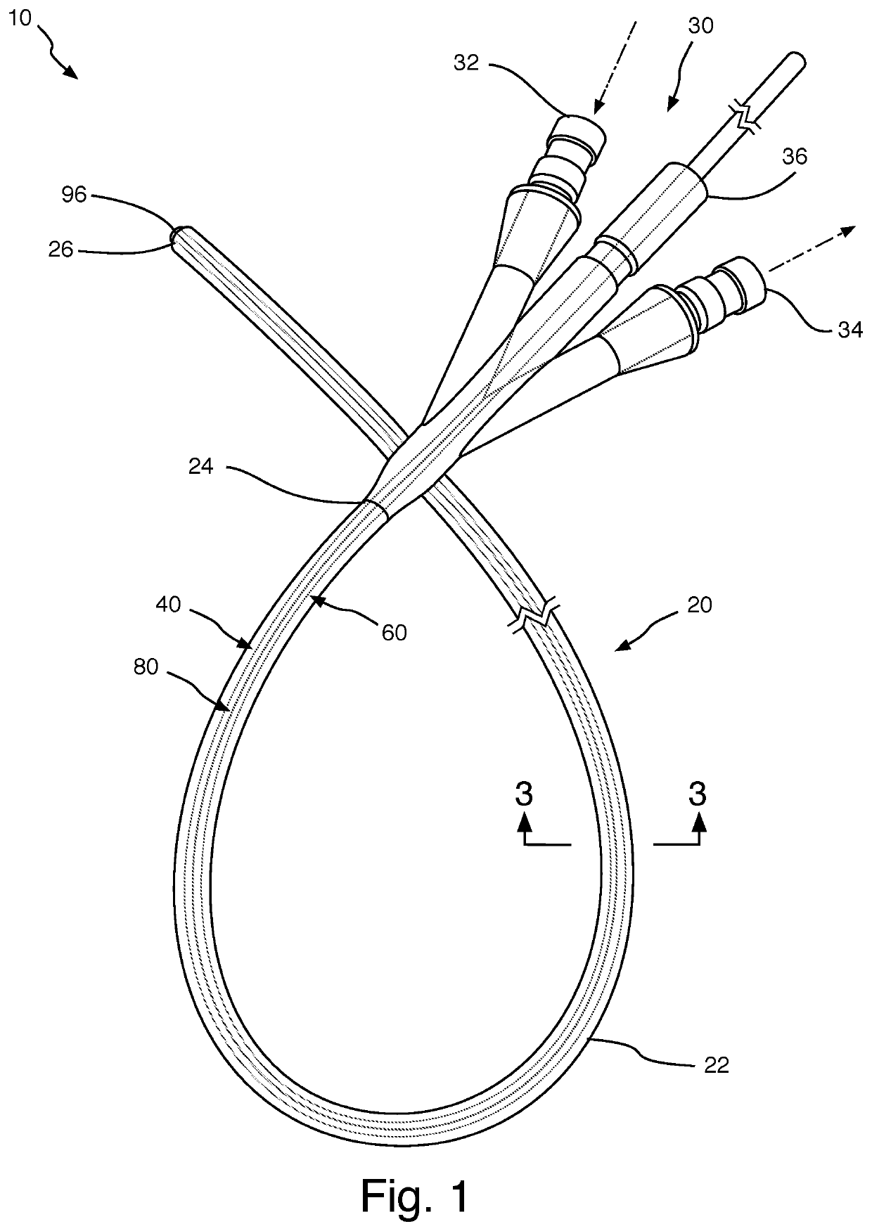
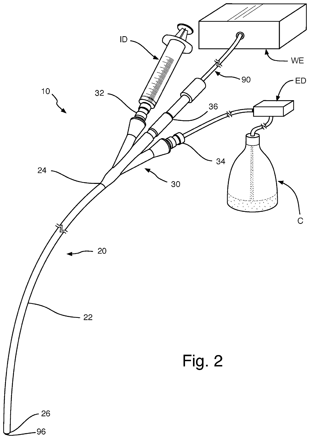
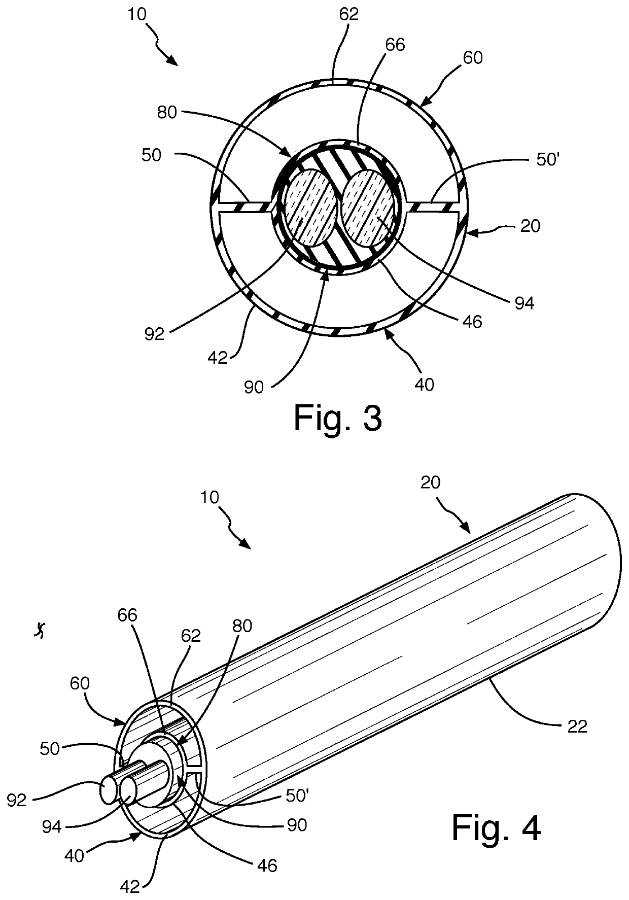
[0056]Referring now to the drawings, the present invention is a catheter for thromboembolic disease with mechanic waves, injection and ejection, and is generally referred to with numeral 10. It can be observed that it basically includes triple-lumen catheter system 20 having first lumen 40, second lumen 60, and third lumen 80.

[0057]As seen in FIGS. 1 and 2, triple-lumen catheter system 20 comprises catheter body 22, proximal end 24, and distal end 26. Proximal end 24 is connected to port assembly 30. First lumen 40, second lumen 60, and third lumen 80 are longitudinal. Port assembly 30 comprises injection port 32, ejection port 34, and emission port 36. Injection port 32 receives injection device ID and interconnects with first lumen 40. Ejection port 34 connects with ejection device ED having container C, and interconnects with second lumen 60. Emission port 36 is connected to wave emitter device WE, whereby mechanical wave emitter 90 passes through third lumen 80.

[0058]As seen in ...


PUM


Abstract

A catheter for thromboembolic disease with mechanic waves, injection, and ejection having a triple-lumen catheter system, whereby a first lumen is for injection, a second lumen is for ejection, and a third lumen has a mechanical wave emitter for wave emissions. The first lumen, the second lumen, and the third lumen are longitudinal, whereby the first lumen and the second lumen are symmetrical and opposite each other, and the third lumen is positioned approximately at a center of the triple lumen catheter system.

Description

BACKGROUND OF THE INVENTION1. Field of the Invention[0001]The present invention relates to medical devices, and more particularly, to catheters for thromboembolic diseases, which have combined mechanic waves, injection, and ejection functions.2. Description of the Related Art[0002]Applicant believes that one of the closest references corresponds to U.S. Pat. No. 5,447,509 A issued to Mills, et al. on Sep. 5, 1995 for Ultrasound catheter system having modulated output with feedback control. However, it differs from the present invention because Mills, et al. teach a method and apparatus for driving an ultrasound transducer coupled to an ultrasound transmission disposed within an elongate catheter that has a modulated output and utilizes feedback control. A modulating signal varying in amplitude and continuous in duration modulates an ultrasound transducer drive signal. The resulting modulated ultrasound transducer drive signal is likewise continuous in duration such that it lacks the...

Claims


Application Information

Patent Timeline
IPC IPC(8): A61B17/22A61M25/00
CPCA61B17/22012A61M2025/0037A61B2017/22079A61M25/0032A61B2017/22081A61B2017/22014A61B2017/22015A61B2017/22084A61B2217/005A61B2217/007A61M2025/0039
Inventor LORENZO, EDUARDO
Owner LORENZO EDUARDO
Learn More