Method and device for producing a winding element

a technology of winding elements and winding wires, which is applied in the manufacture of inductance/transformers/magnets, electrical apparatus, dynamo-electric machines, etc., can solve the problems of low production efficiency, low filling factor, and low efficiency of winding elements, and achieve no performance-reducing air gaps, simple configuration, and high filling factor

Active Publication Date: 2022-05-17
FRAUNHOFER GESELLSCHAFT ZUR FOERDERUNG DER ANGEWANDTEN FORSCHUNG EV
View PDF10 Cites 0 Cited by
  • Summary
  • Abstract
  • Description
  • Claims
  • Application Information

AI Technical Summary

Benefits of technology

[0008]Compared to prior art and a complex multi-stage forming technology taught there, both the winding process to give the winding element its desired three-dimensional shape with several helically formed turns wound one on top of the other as well as the cross-sectional deformation of the coil wire by way of the method described above and the device described above take place simultaneously and / or with a tool of a highly simple configuration, so that winding elements exhibiting a high filling factor and virtually no performance-reducing air gaps (as shown in the left-hand half of the drawing of FIG. 13) can be economically produced in a one-step and / or extremely simple and flexible manufacturing process.

Problems solved by technology

Due to the round shape of wire 2, gaps filled with air between the individual turns of a coil or between adjacent coils are unavoidable, which leads to relatively poor electrical parameters.
A drawback of the above flat wire coils, however, is that such coils are still very complex and therefore very expensive to produce.
However, the two-stage nature of the manufacturing process (requiring pre-winding and a separate embossing step) and the complexity of the required embossing tool, consisting of several segments axially disposed above each other, makes economic and flexible coil production difficult.
This is especially true for prototyping and small batch production of coils where long throughput times and tooling costs are unacceptable.

Method used


Image

  • Method and device for producing a winding element
  • Method and device for producing a winding element
  • Method and device for producing a winding element

Examples


Embodiment Construction

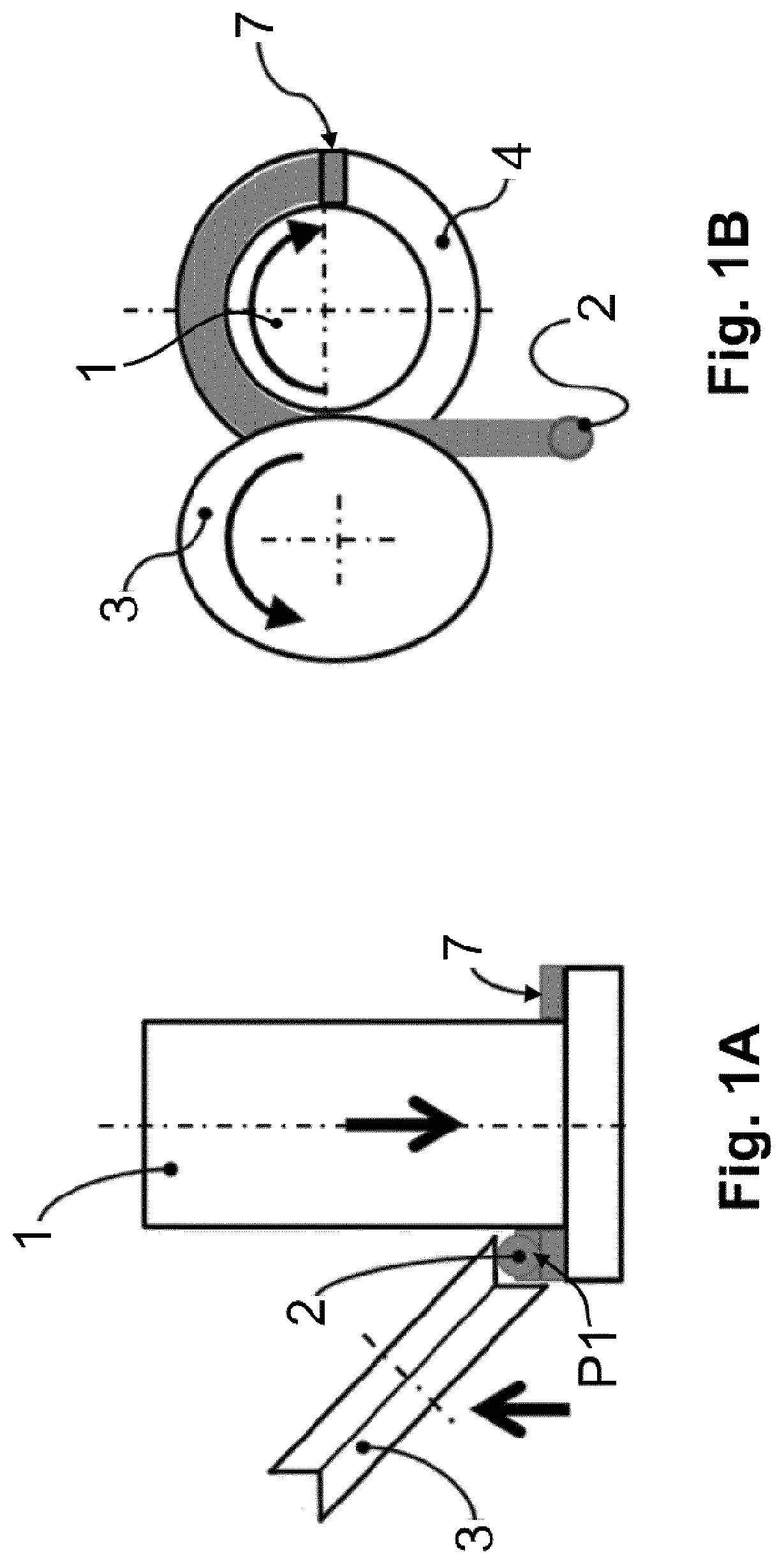
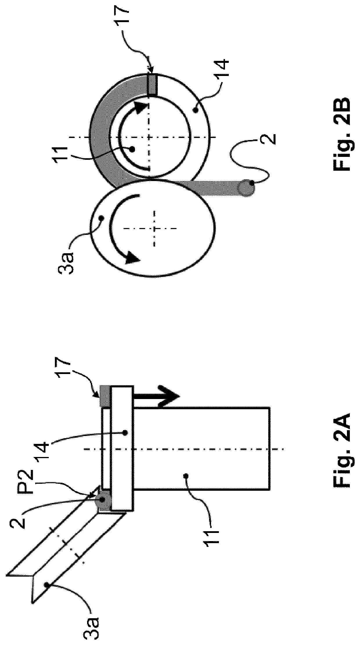
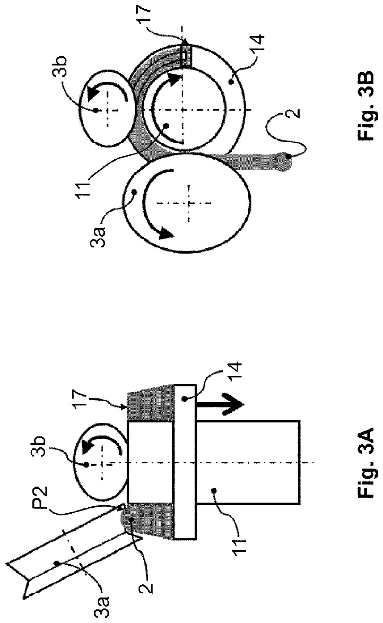
[0018]The approach illustrated in the embodiments of FIGS. 1A and 1B, 2A and 2B, 3A and 3B, 6 and 7 is to transform supplied wire 2 with respect to the cross section to a desired shape (e.g. trapezoidal shape) by use of a shaping tool (e.g., a section roller 3, 3a, 3b, 13) when winding wire 2 (in particular copper wire) with a round or otherwise shaped (e.g., oval or rectangular) initial cross section about a rotating mandrel 1, 11, 21, 31 which represents the interior of resulting winding element 7, 17, 27, 37.

[0019]The simultaneous winding of winding element 7, 17, 27, 37 and cross-sectional deformation of supplied wire 2 can be achieved by the devices shown in the figures. A first device according to FIGS. 1A and 1B is shown in a side view and a top view perpendicular thereto. This device comprises a mandrel 1 on which a radially projecting fixed shoulder 4 is formed. Mandrel 1 and shoulder 4 are moved to rotate about their longitudinal axis during the winding process by a drive,...


PUM

PropertyMeasurementUnit
angleaaaaaaaaaa
forming forceaaaaaaaaaa
angleaaaaaaaaaa

Abstract

The invention provides a method and a device for producing a winding element from a supplied wire, in particular from a round copper wire, said method and device allowing the economical and flexible production of a winding element which, when subsequently used in the field of electrical engineering as a coil or inductor fitted in a stator, ensures the highest possible groove filling factor. For this purpose, the wire is wound to a three-dimensional shape and the cross section of the wire is changed simultaneously, as a result of which separate method steps and therefore tool arrangements for three-dimensional winding of the wire as well as the change of the cross-section of the wire can advantageously be dispensed with.

Description

FIELD OF THE INVENTION[0001]The invention relates to a method and a device for producing a winding element from a wire, such as an electrotechnical coil made of a round copper wire.BACKGROUND OF THE INVENTION[0002]To enhance the performance of electrical machines (such as generators and electric motors) and other power components (such as transformers and inductors), coils made of round wire are increasingly being replaced with rectangular wire or wires otherwise adapted in cross section. With such cross-sectional adaptations, the filling factor, i.e. the ratio of wire cross sections to the entire winding space, which is limited to a maximum value of only about 55% due to the geometric conditions in packetized round wires, can be increased to an order of about 90%.[0003]This significant increase in the groove filling factor is clearly evident from FIG. 13 which shows several coils inserted in the stator of a machine. The coils of wildly wound round wire 2 shown in the right-hand hal...

Claims


Application Information

Patent Timeline
Patent Type & Authority Patents(United States)
IPC IPC(8): H01F41/00H01F41/098H01F41/061H01F41/077H02K15/04
CPCH01F41/098H01F41/061H01F41/077H02K15/04
Inventor WERNER, MARKUS
Owner FRAUNHOFER GESELLSCHAFT ZUR FOERDERUNG DER ANGEWANDTEN FORSCHUNG EV
Why Eureka
Try Eureka