Supercharge Your Innovation With Domain-Expert AI Agents!

Connector

a technology of connecting rods and connectors, applied in the direction of charging stations, transportation and packaging, coupling device connections, etc., can solve the problems of sleeves

Active Publication Date: 2022-05-24
JAPAN AVIATION ELECTRONICS IND LTD
View PDF15 Cites 1 Cited by
  • Summary
  • Abstract
  • Description
  • Claims
  • Application Information

AI Technical Summary

Benefits of technology

The present invention provides a connector that allows for easy control of the tilting of a contact with respect to a sleeve member. This is achieved by the sleeve member having front protrusions that come into contact with the abutment portion of the contact. By adjusting the protruding dimension of one or more of the front protrusions, the tilt of the contact can be easily adjusted. This is simpler than adjusting the tilt of the entire front-end surface of the sleeve member.

Problems solved by technology

However, considering production variability, it is very hard that the front-end surface of the sleeve member 940 is made to be perpendicular to a longitudinal direction of the sleeve member 940.

Method used


Image

  • Connector
  • Connector
  • Connector

Examples


Embodiment Construction

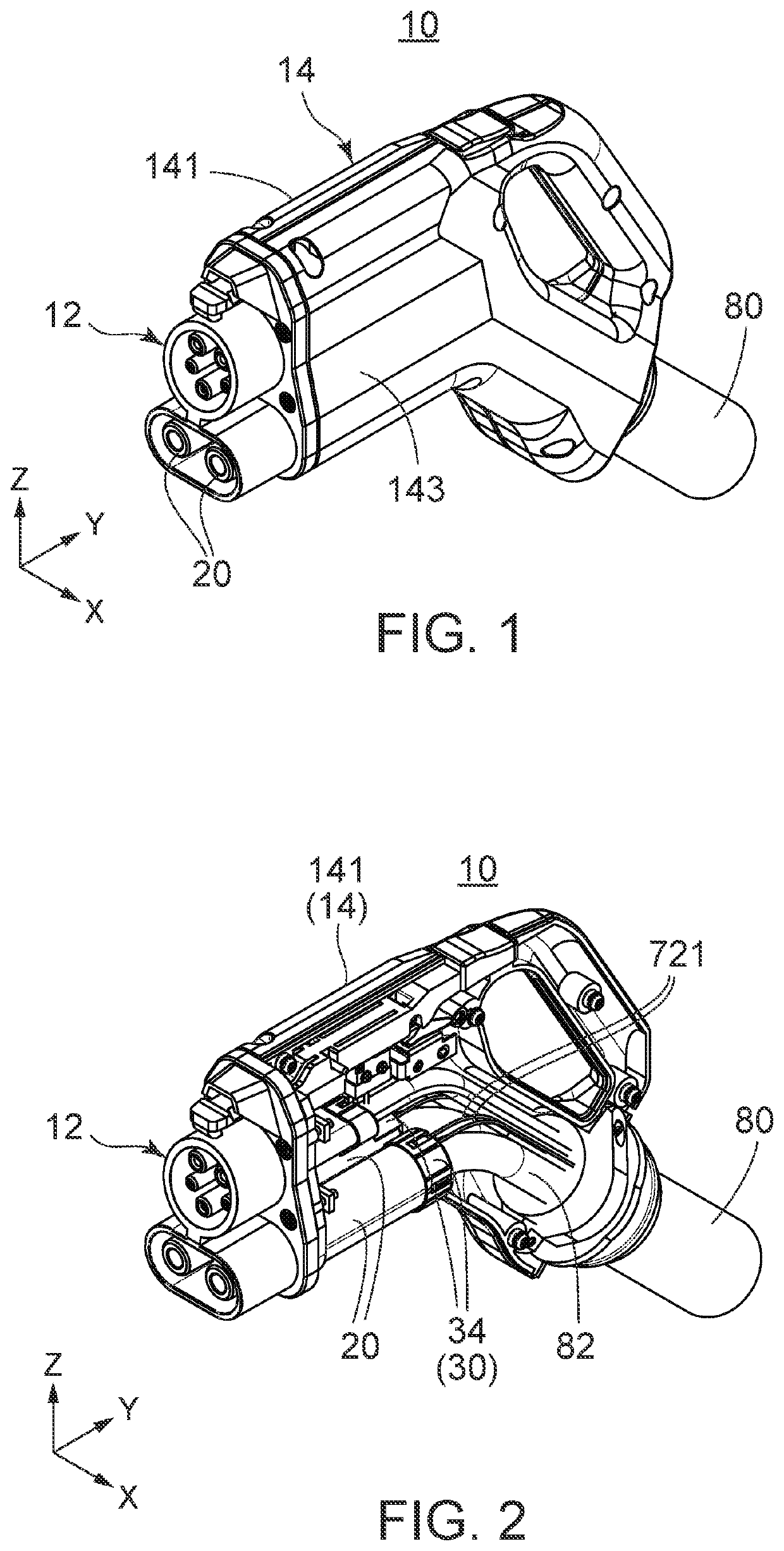
[0034]Referring to FIGS. 1 and 3, a connector 10 according to an embodiment of the present invention is a charging connector for an electric vehicle, wherein it is attached to an end of a cable 80. However, the present invention is not limited thereto. The present invention is applicable to connectors for every use.

[0035]As shown in FIGS. 1 and 3, the connector 10 is provided with a mating portion 12 and a body 14. The body 14 has a base shell 141 and a cover shell 143.

[0036]As shown in FIGS. 2 and 4, the base shell 141 is provided with housings 20. As understood from FIGS. 1, 3 and 4, in the present embodiment, the number of the housings 20 is two. However, the present invention is not limited thereto. The connector of the present invention should be provided with at least one housing 20. Moreover, the housings 20 may not be provided to the base shell 141 but be exposed outside.

[0037]As understood from FIGS. 2 and 4, holders 30 are attached to the housings 20, respectively. In deta...


PUM


Abstract

A connector comprises a housing, a holder, a contact, an electrical wire and a sleeve member. The contact is accommodated in a contact accommodation portion of the housing at least in part. The holder is attached to the housing and defines a rear end of the contact accommodation portion. An electrical wire is connected to the contact and extends outside thorough a through hole of the holder. The sleeve member has a main portion and three or more front protrusions. The main portion extends in a front-rear direction and has a C-shape section in a plane perpendicular to the front-rear direction. Each of the front protrusions protrudes forward from a front end of the main portion. The sleeve member is attached to the contact to accommodate a part of the contact and a part of the electrical wire in the main portion and located between an abutment portion and the holder. At least three of the front protrusions are brought into abutment with the abutment portion of the contact.

Description

BACKGROUND OF THE INVENTION[0001]This invention relates to a connector, particularly to a connector provided with a contact which is connected to an electrical wire and accommodated in a housing.[0002]A connector provided with a contact which is connected to an electrical wire and accommodated in a housing is disclosed in JP2010-55809A (Patent Document 1) for example.[0003]As shown in FIG. 20, a connector 90 of Patent Document 1 is provided with a terminal metal 910, a connector housing 920, a rear holder 930, a sleeve member 940, a center packing 950 and a rear packing 960.[0004]As shown in FIG. 21, the connector housing 920 is provided with a terminal accommodation room 922. The terminal metal 910 is accommodated in the terminal accommodation room 922 and connected to an electrical wire 970. The rear holder 930 is attached to a rear portion of the connector housing 920 and fills the terminal accommodation room 922 in part.[0005]As shown in FIG. 21, the terminal metal 910 has a fla...

Claims


Application Information

Patent Timeline
Patent Type & Authority Patents(United States)
IPC IPC(8): H01R13/58H01R13/52
CPCH01R13/5841H01R13/5205H01R2201/26B60L53/16H01R13/40H01R13/521H01R13/506H01R13/4367Y02T10/70Y02T10/7072Y02T90/14
Inventor TAKAGI, YOUHEI
Owner JAPAN AVIATION ELECTRONICS IND LTD
Features
  • R&D
  • Intellectual Property
  • Life Sciences
  • Materials
  • Tech Scout
  • Unparalleled Data Quality
  • Higher Quality Content
  • 60% Fewer Hallucinations
Learn More