
Stepped drill bit with alternately sharpened edges to clean-out obscured fastener openings in cross laminated timber joints

a cross-laminated timber and drill bit technology, applied in the field of drill bits, can solve problems such as damage to wood fibers, change of size and shape, metal exposed to external forces,

Active Publication Date: 2022-06-07
THE MILLER DOWEL CO
View PDF4 Cites 0 Cited by
  • Summary
  • Abstract
  • Description
  • Claims
  • Application Information

AI Technical Summary

Benefits of technology

The drill bit effectively reshapes the distorted openings to accommodate dowels, ensuring proper alignment and secure fastening without damaging the original hole dimensions, thereby maintaining the structural integrity of the CLT connections.

Problems solved by technology

The materials have been found to be as strong and durable as standard construction materials, such as steel and concrete; but new methods of fastening the construction elements have become necessary as a result of the science of sustainable materials and the problems associated with the use of standard fasteners with these specialized materials.
Metal exposed to external forces can oxidize, changing size and shape and causing damage to the wood fibers.
Further, tying CLT with such standard fasteners which tend to squeeze the wood elements together, by the force of tightening the fastener, can cause the surface wood fibers to be damaged.
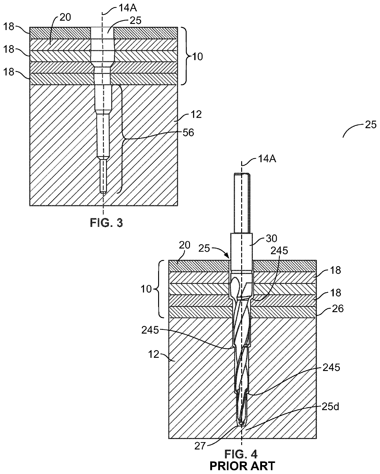
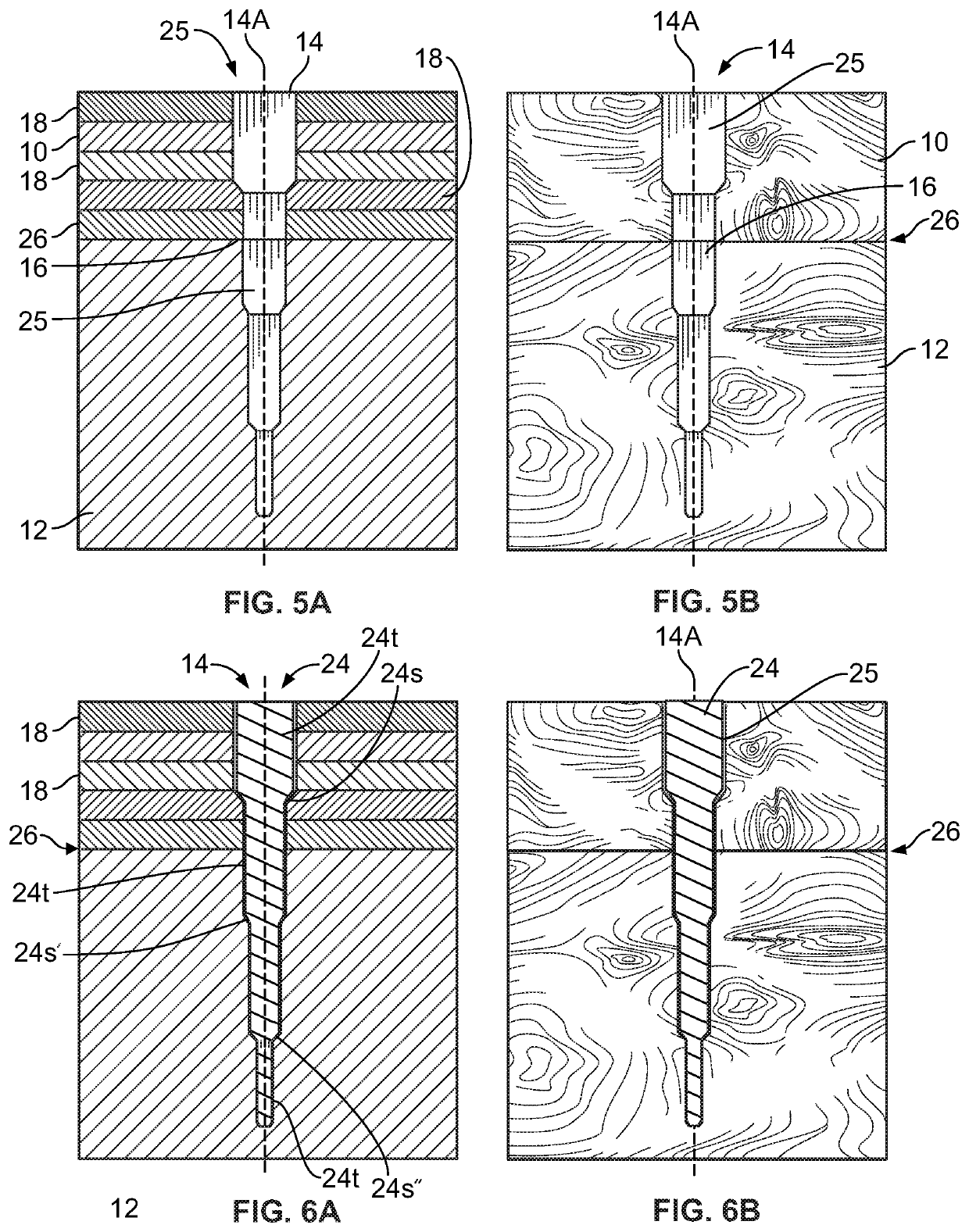
Unfortunately, it has been found that the holes thus made, which comprise stepped sections wherein each step is generally concentrically oriented about a single axis there through, by the time the panel is delivered to the construction site, have been partially blocked or obscured due to the shifting of the constituent wood pieces used in the construction of a CLT panel.
It can be seen in such panels that there no longer exists a single axis with all elements concentric thereto, through the length of the opening thus impeding the easy placement of a dowel therein.
While in most cases the shifting is slight, it has been found that the shifting is generally sufficient to cause the need for extra force to drive the dowel and often, with stepped dowels, one or more of the steps can no longer be well filled by the dowel.
This will result in a weakened connection that can prove fatal to the strength of the structure.

Method used


Image

  • Stepped drill bit with alternately sharpened edges to clean-out obscured fastener openings in cross laminated timber joints
  • Stepped drill bit with alternately sharpened edges to clean-out obscured fastener openings in cross laminated timber joints
  • Stepped drill bit with alternately sharpened edges to clean-out obscured fastener openings in cross laminated timber joints

Examples


Embodiment Construction

[0033]While the present invention is susceptible of embodiment in various forms, there is shown in the drawings a number of presently preferred embodiments that are discussed in greater detail hereafter. It should be understood that the present disclosure is to be considered as an exemplification of the present invention, and is not intended to limit the invention to the specific embodiments illustrated. It should be further understood that the title of this section of this application (“Detailed Description of the Illustrative Embodiment”) relates to a requirement of the United States Patent Office, and should not be found to limit the subject matter disclosed herein.

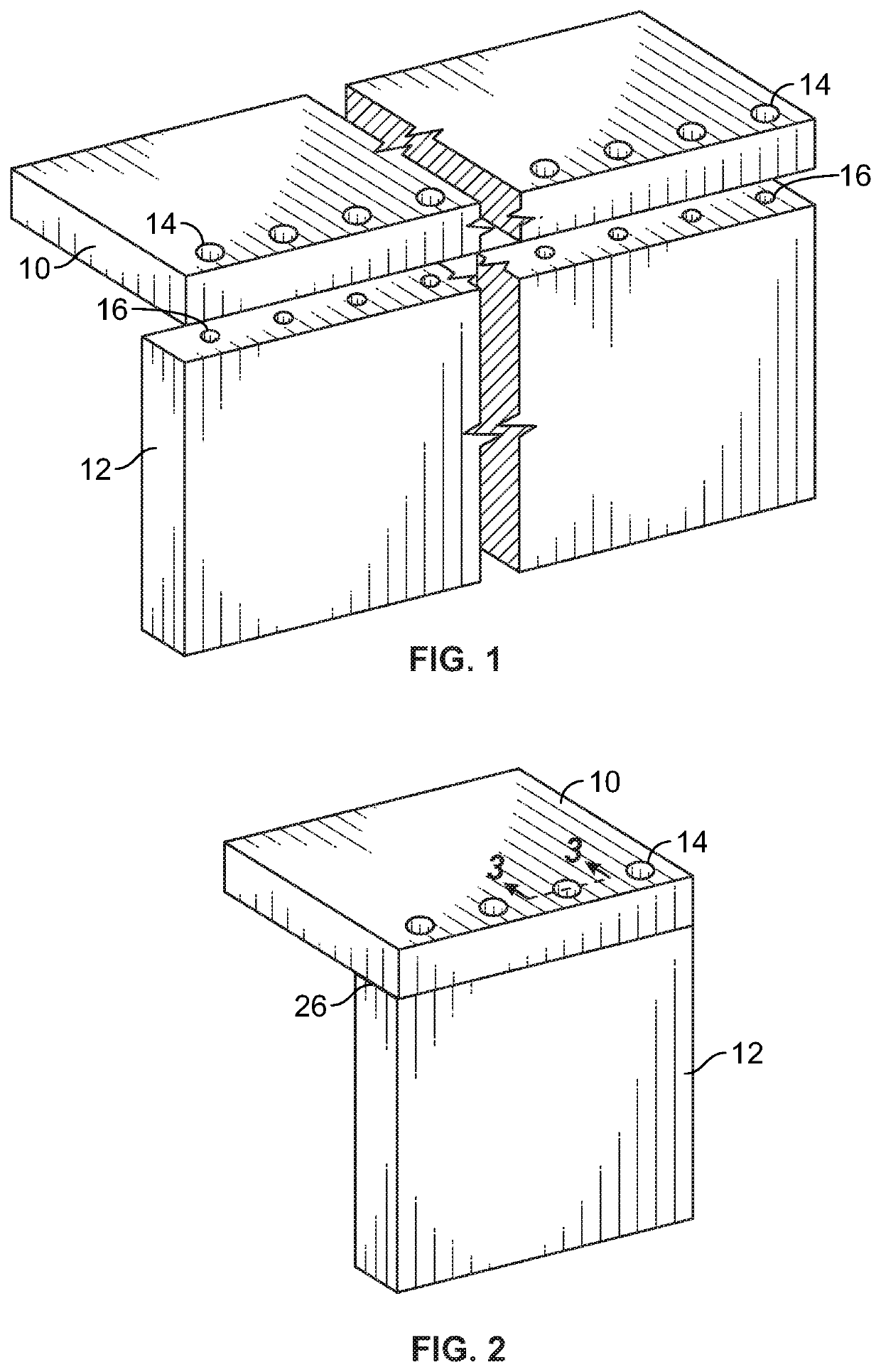
[0034]Referring to the drawings, FIGS. 1 and 2 show one type of joinder of two wood panels that is subject to the use of the drill bit of the present invention. Element 10 and element 12 are to be joined together at approximately a right angle, using fastener openings 14 in element 10 and fastener opening 16 in element...


PUM


Abstract

A drill bit for use with construction using cross laminated timbers (CLT) is provided. The bit has both sharpened and dull portions of the cutting element of the bit, so that it can clean-out an opening in the CLT that has been partially obscured by shifts in the laminated constituents of the CLT, without elongating or otherwise changing the shape of the fastener opening. The use of the bit is made at the construction site in fastener openings previously made and otherwise obscured, thereby allowing the quick assembly and construction of a structure made of CLT.

Description

FIELD OF THE INVENTION[0001]The present invention concerns the field of Cross Laminated Timber (CLT) construction, dowels used as fasteners and on-sight preparation for the joinder of construction elements. More particularly the present invention concerns a drill bit used to sort-out the premade openings into which dowels for joining two construction elements are driven. The drill bit is employed so that, in the event that the constituents of the construction elements have slipped since fastener openings were created, those opening can be sorted to permit the dowel, or fastener, to be nominally inserted therein to complete the construction process.BACKGROUND OF THE INVENTION[0002]Construction of large elements, using cross laminated timbers (CLT) is a relatively new field when it comes to the use of such materials to create large structures. The use of CLT construction is moving forward in places where the use of sustainable materials and contemporary design are important. The mater...

Claims


Application Information

Patent Timeline
Patent Type & Authority Patents(United States)
IPC IPC(8): B23B51/00
CPCB23B51/009B27G15/00
Inventor MILLER, MICHAEL R.
Owner THE MILLER DOWEL CO
Learn More