Battery pack

a battery cell and battery technology, applied in cell components, electrical equipment, electrochemical generators, etc., can solve the problems of high temperature of the battery cell, lack of heat transfer route, and thermal impact spreading to the battery cells surrounding abnormal battery cells, so as to reduce the variation in temperature, increase energy density, and inhibit the effect of thermal impa

Active Publication Date: 2022-06-07
PANASONIC INTELLECTUAL PROPERTY MANAGEMENT CO LTD
View PDF5 Cites 3 Cited by
  • Summary
  • Abstract
  • Description
  • Claims
  • Application Information

AI Technical Summary

Benefits of technology

[0004]A battery pack contains the battery modules that each include the plurality of the electrically connected single battery cells. If part of the battery cells in the battery pack abnormally generates heat in the event of an anomaly, a thermal impact may spread to the battery cells surrounding the abnormal battery cell. Thus, a possible countermeasure consists of installing a low-heat-conductive insulator as a separator between the adjacent battery cells in each of the battery modules to hinder the transmission of heat from the battery cell that has abnormally generated heat to the other battery cells. Unfortunately, this countermeasure does not provide a heat transfer route used to transmit heat from the battery cell that has abnormally generated heat to constituents of the battery pack other than the battery cells adjacent to the abnormal battery cell in the same battery module and thus requires a substantial amount of a heat insulating material to ensure that a thermal impact does not spread to the adjacent battery cells. This causes each of the battery modules and the battery pack to have a decreased energy density with respect to a constant entire volume.
[0005]There is a possibility that most of a surface of each of the battery cells is covered with a heat insulating material. As a result, heat generated from the battery cell by charging or discharging under normal use conditions is less likely to be released or discharged to an outside. This can cause temperature of the battery cell to get high and damage an electrical characteristic of the battery cell. Further, heat insulation is provided between the plurality of battery cells. This increases variation in temperature among the battery cells, causing a difference in battery characteristic.
[0007]The battery pack according to the present disclosure can inhibit the spread of a thermal impact created when part of the battery cells abnormally generates heat, provide an increased energy density, and reduce variation in temperature among the battery cells under normal use conditions. Under normal use conditions, the battery pack can prevent the battery cells from reaching an excessively high temperature.

Problems solved by technology

If part of the battery cells in the battery pack abnormally generates heat in the event of an anomaly, a thermal impact may spread to the battery cells surrounding the abnormal battery cell.
Unfortunately, this countermeasure does not provide a heat transfer route used to transmit heat from the battery cell that has abnormally generated heat to constituents of the battery pack other than the battery cells adjacent to the abnormal battery cell in the same battery module and thus requires a substantial amount of a heat insulating material to ensure that a thermal impact does not spread to the adjacent battery cells.
This can cause temperature of the battery cell to get high and damage an electrical characteristic of the battery cell.
This increases variation in temperature among the battery cells, causing a difference in battery characteristic.

Method used


Image

  • Battery pack
  • Battery pack
  • Battery pack

Examples


Embodiment Construction

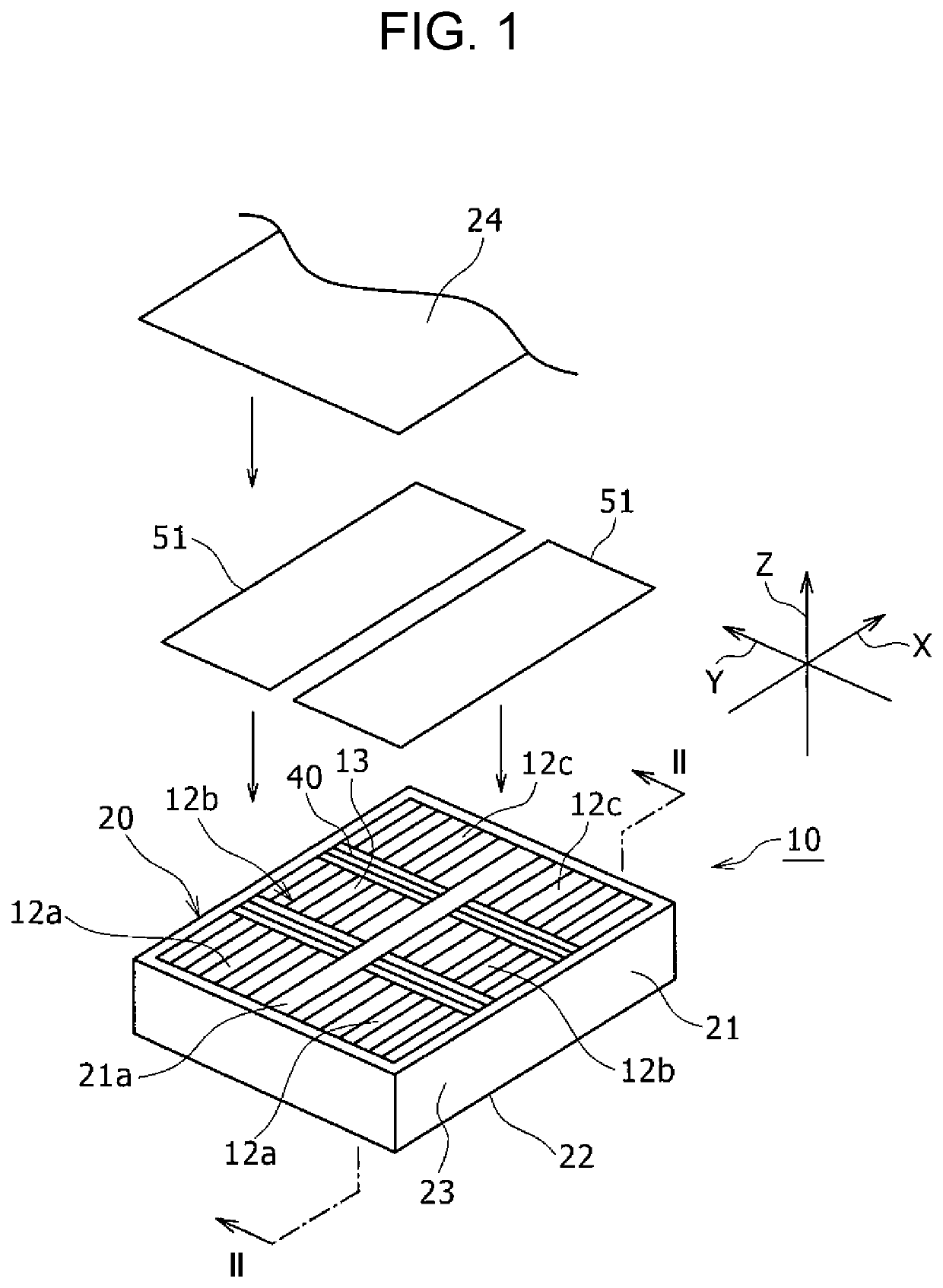
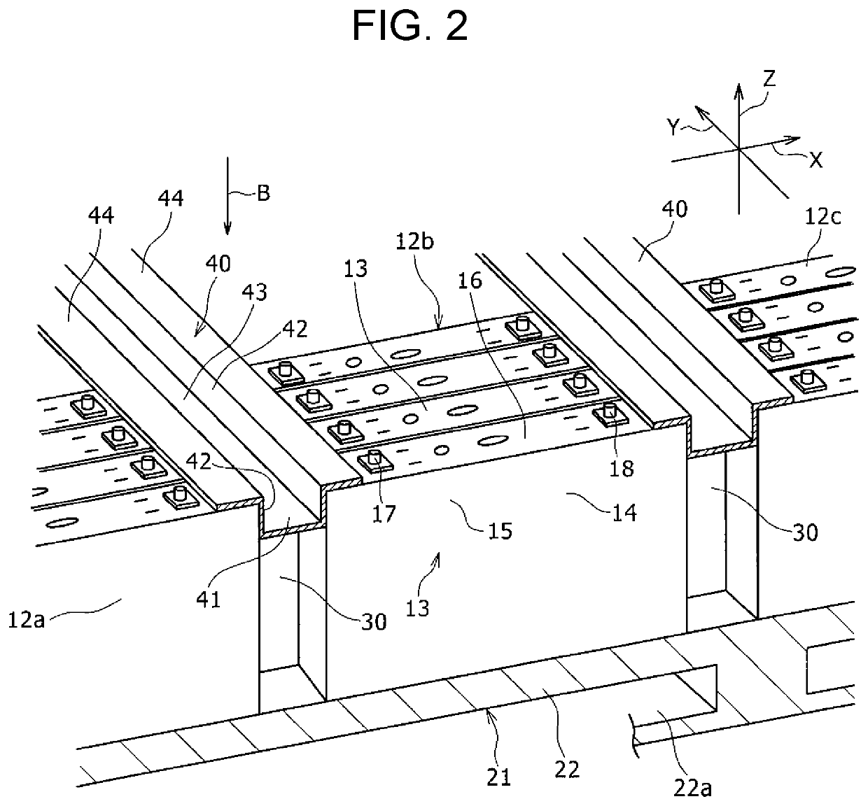
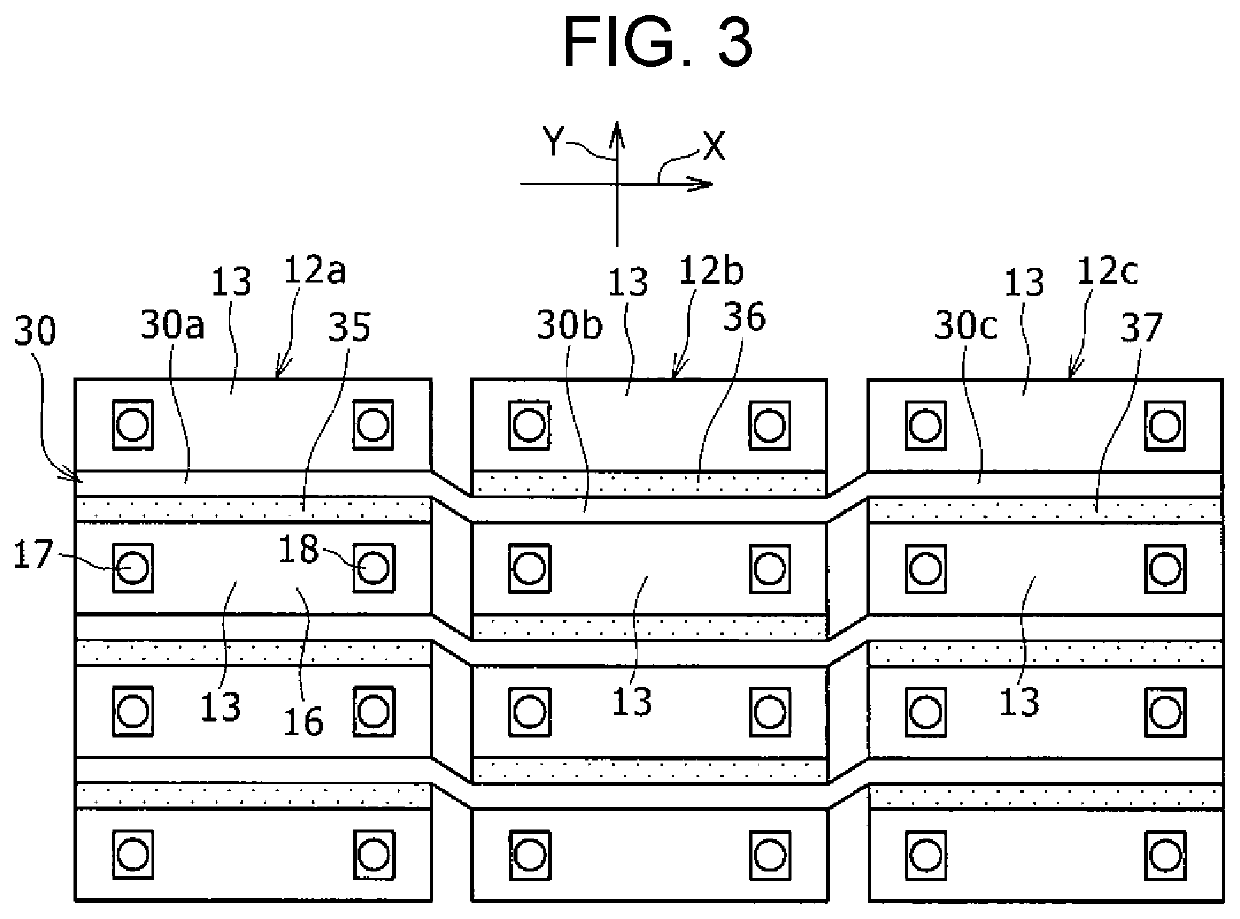
[0015]A battery pack according to an example of an exemplary embodiment will be described below in detail. Drawings referenced in a description of the exemplary embodiment are schematically drawn, and dimensions and proportions of configuration elements illustrated in the drawings may differ from those of actual components. Thus, specific dimensions and proportions should be understood in view of the following description. In the description given herein, “substantially identical” means absolutely identical, as well as virtually identical, for example. Other words modified by “substantially” should be interpreted in the same manner. An “end” of an object means an edge and a surrounding portion of the object. Shapes, materials, piece counts, and other particulars described below are provided for the purpose of illustration and may be changed depending on specifications of battery packs. In the following description, identical or equivalent components are denoted by identical referenc...


PUM

PropertyMeasurementUnit
thermal conductivityaaaaaaaaaa

Abstract

A battery pack includes first and second battery modules arranged in a first direction. In the first battery module, a first heat transfer part and a first heat insulator are disposed between battery cells adjacent in a second direction orthogonal to the first direction. In the second battery module, a second heat transfer part and a second heat insulator are disposed between battery cells adjacent in the second direction. The first heat transfer part constitutes a part of a heat transfer component that is put across and connected to both the first and the second battery modules. The first heat transfer part is connected to one of the battery cells in the first battery module so as to enable heat transfer. The second heat transfer part constitutes another part of the heat transfer component and is connected to one of the battery cells in the second battery module.

Description

TECHNICAL FIELD[0001]The present disclosure relates to a battery pack.BACKGROUND ART[0002]A conventionally known battery pack includes a plurality of battery modules. Further, the plurality of battery modules are formed independently of one another. For instance, PTL 1 describes a configuration in which a plurality of single cells (battery cells) that are prismatic batteries are disposed side by side with respective spacers therebetween, and long bind bars are disposed on both widthwise sides of the plurality of single cells. In this configuration, both ends of each bind bar are fixed to two end plates that are disposed at respective ends of an array of the plurality of single cells in a battery module. In the battery module, connection plates are disposed at both height-wise ends of the single cells, and both ends of each connection plate are fixed to the end plates. The plurality of battery modules are arranged in a height-wise direction, and an intermediate bracket is disposed be...

Claims


Application Information

Patent Timeline
Patent Type & Authority Patents(United States)
IPC IPC(8): H01M10/658H01M10/613H01M10/647H01M10/6555H01M50/209H01M10/6561H01M10/6557H01M10/6567
CPCH01M10/658H01M10/613H01M10/647H01M10/6555H01M10/6557H01M10/6561H01M10/6567H01M50/209Y02E60/10
Inventor SHIMIZU, KEISUKEMOTOKAWA, SHINYAMURAYAMA, CHIFUMI
Owner PANASONIC INTELLECTUAL PROPERTY MANAGEMENT CO LTD
Why Eureka
Try Eureka