
Semiconductor patterning process

a technology of semiconductors and patterns, applied in semiconductor/solid-state device manufacturing, basic electric elements, electric instruments, etc., can solve the problems of limiting the application range of these processes, affecting the design of semiconductors, so as to achieve the effect of simple process steps, greater design flexibility, and large feature siz

Active Publication Date: 2022-06-21
POWERCHIP SEMICON MFG CORP
View PDF7 Cites 0 Cited by
  • Summary
  • Abstract
  • Description
  • Claims
  • Application Information

AI Technical Summary

Benefits of technology

[0005]The invention provides a semiconductor patterning process having greater design flexibility and simple process steps.
[0017]Based on the above, in the invention, for the initial mask patterns with the same feature size, a pattern with a greater feature size may be formed as needed without additional complicated steps, and therefore greater design flexibility and simple process steps may be achieved. In addition, when defining a mask pattern with a greater feature size, the lithography process may have a greater process window. In addition, the mask pattern applied to a peripheral region may be defined without performing a plurality of lithography processes, and therefore influence to the pattern of the peripheral region from a plurality of lithography processes may be prevented.

Problems solved by technology

However, the above various patterning processes may not meet the existing pattern design requirements.
For example, the above various patterning processes may often only produce patterns with the same feature size, thus limiting the application range of these processes.
In addition, a plurality of photomasks are needed in the various patterning processes above, thus resulting in higher production costs, and the accuracy of the resulting device pattern is readily affected.

Method used


Image

  • Semiconductor patterning process
  • Semiconductor patterning process
  • Semiconductor patterning process

Examples


Embodiment Construction

[0021]The semiconductor patterning process of the invention may be applied to various pattern designs. For example, the semiconductor patterning process of the invention may be applied to designs including a plurality of patterns with the same feature size and designs including a plurality of patterns with different feature sizes. In other words, the semiconductor patterning process of the invention may be highly flexible in pattern design. The semiconductor patterning process of the invention is described in detail below.

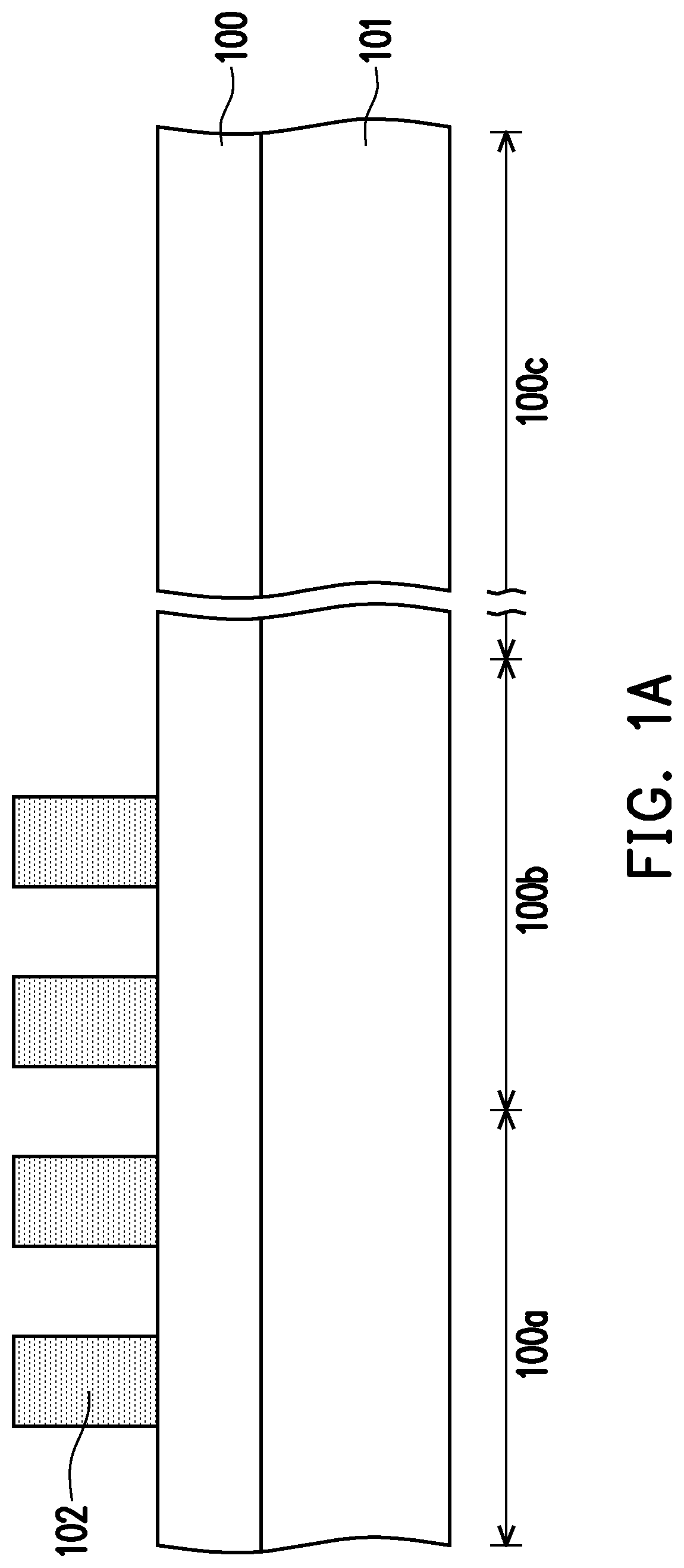
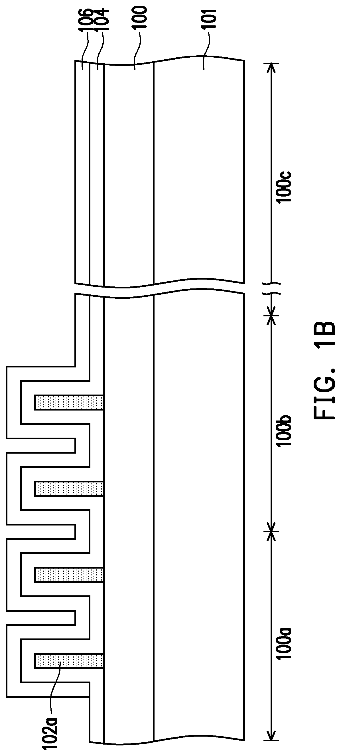
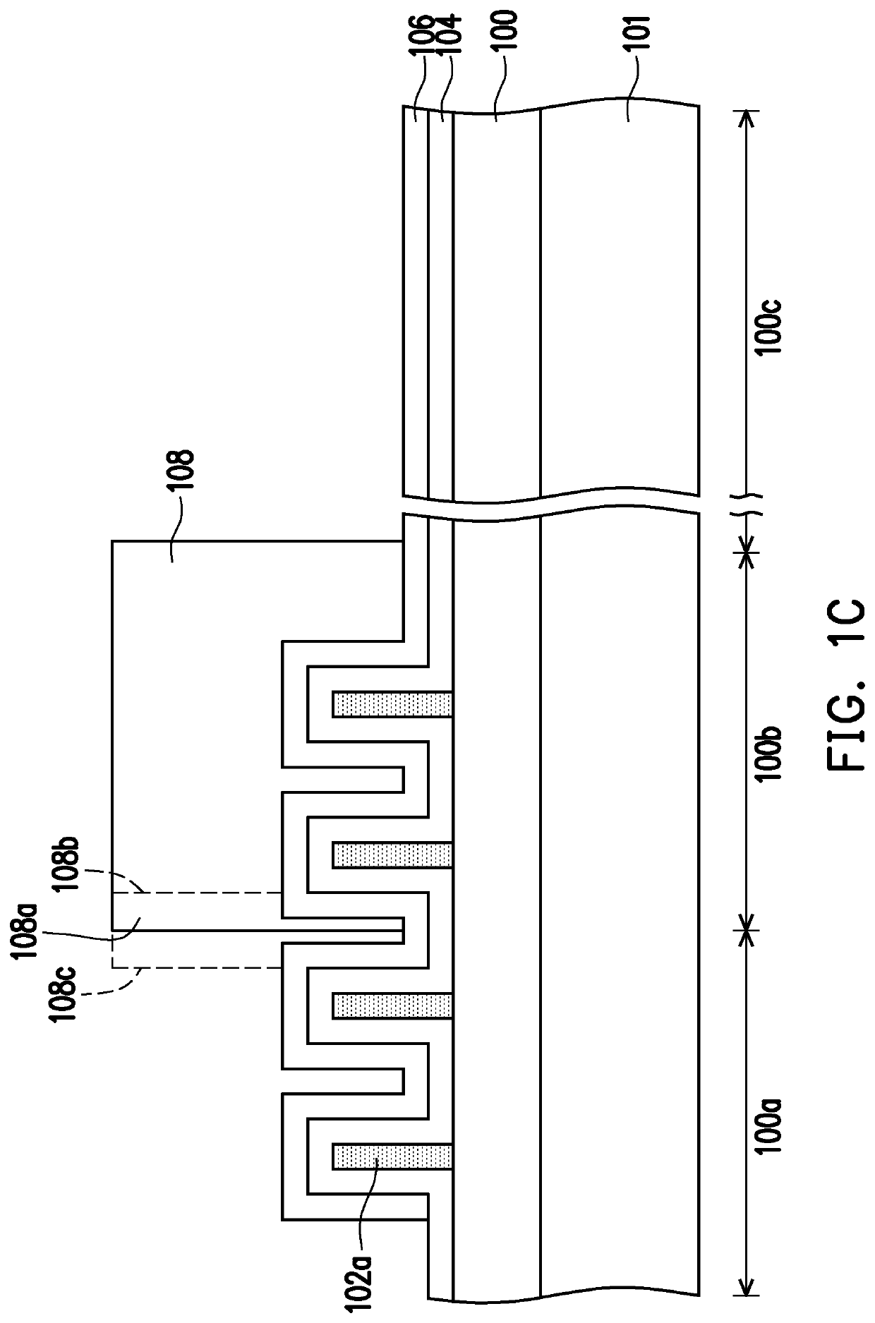
[0022]FIG. 1A to FIG. 1G are cross-sectional views of a semiconductor patterning process according to the first embodiment of the invention. In the present embodiment, the semiconductor patterning process is applied to designs including a plurality of patterns with the same feature size.

[0023]First, referring to FIG. 1A, a plurality of initial mask patterns 102 are formed on a substrate 100. The substrate 100 is a target substrate, that is, a substrate to be patter...


PUM

PropertyMeasurementUnit
sizeaaaaaaaaaa
feature sizeaaaaaaaaaa
flexibilityaaaaaaaaaa

Abstract

A semiconductor patterning process includes the following steps. A substrate is provided, wherein the substrate has a first region, a second region, and a third region, and the second region is located between the first region and the third region. A plurality of initial mask patterns are formed on the substrate. A first mask material layer is conformally formed on the substrate. A first mask pattern is formed above at least two adjacent initial mask patterns in the second region and on the first mask material layer in between, and a second mask pattern is formed on the first mask material layer on sidewalls of remaining initial mask patterns. A portion of the first mask material layer is removed using the first mask pattern and the second mask pattern as a mask to form a final mask pattern on the substrate.

Description

CROSS-REFERENCE TO RELATED APPLICATION[0001]This application claims the priority benefit of Taiwan application serial no. 109114871, filed on May 5, 2020. The entirety of the above-mentioned patent application is hereby incorporated by reference herein and made a part of this specification.BACKGROUND OF THE INVENTIONField of the Invention[0002]The invention relates to a semiconductor patterning process.Description of Related Art[0003]With the rapid development of the integrated circuit industry, as the demand for circuit integration is increased, the size of the entire circuit device needs to be reduced and the requirements for the resolution of the lithography process are increased. At present, in order to overcome the limitations of light source resolution in the lithography process, the self-aligned double patterning (SADP) process, the self-aligned triple patterning (SATP) process, and the self-aligned quadruple patterning (SAQP) process are gradually developed to increase the d...

Claims


Application Information

Patent Timeline
Patent Type & Authority Patents(United States)
IPC IPC(8): H01L21/033
CPCH01L21/0338H01L21/0335H01L21/0337H10B41/42
Inventor WANG, ZIH-SONG
Owner POWERCHIP SEMICON MFG CORP
Learn More